


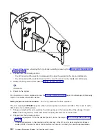


2)
Increment
to
A1
and
press
Enter
.
This
will
send
out
a
Rack
Power
On
command
on
the
SPCN
Network
which
will
restore
power
to
the
expansion
tower
or
unit,
which
has
become
powered
off.
24.
Were
you
sent
here
from
a
tower
card
remove
and
replace
procedure?
v
No:
Continue
with
the
next
step.
v
Yes:
Choose
from
the
following
options:
–
If
you
have
not
set
the
configuration
ID,
return
to
the
tower
card
remove
and
replace
procedure
to
set
it.
–
If
you
have
already
set
the
configuration
ID,
then
continue
with
the
next
step
of
this
procedure.
25.
From
the
Packaging
Hardware
Resources
display,
select
Associated
Logical
Resource(s)
for
the
expansion
tower
or
unit.
The
Logical
Hardware
Resources
Associated
a
Packaging
Resource
display
shows
the
status
of
devices
and
IOPs.
When
all
expected
resources
appear
with
an
operational
status,
work
with
the
customer
to
bring
the
system
to
the
operational
state.
Note:
For
V4R3
and
following
(more
recent)
releases,
a
resource
that
has
been
removed
will
show
a
status
of
″
Not
Connected
″
.
For
earlier
systems
the
status
will
show
as
″
Disabled
″
.
Work
with
the
customer
to
restart
all
bus
activity:
v
Start
all
subsystems
that
were
ended.
v
Vary
on
all
devices,
lines,
and
controllers
for
the
expansion
tower
or
unit
that
was
powered
off.
v
Start
customer
applications.
Was
the
tower
configured
as
a
switchable
tower
under
iSeries
OptiConnect
for
HSL
when
you
entered
this
procedure?
v
Yes
:
Continue
with
the
next
step.
v
No
:
If
you
moved
the
ac
power
cords
of
an
expansion
unit
from
this
tower
to
an
alternate
ac
power
source
during
this
procedure,
then
move
them
back
to
this
expansion
tower.
Move
only
one
of
the
expansion
unit’s
ac
power
cords
at
a
time
to
this
tower
to
prevent
the
expansion
unit
from
loosing
ac
power.
This
ends
the
procedure.
26.
Did
you
change
the
tower’s
mode
to
Private
using
HSM?
v
No
:
Continue
with
the
next
step.
v
Yes
:
Work
with
the
customer
to
restore
the
mode
of
the
tower
to
Switchable
using
the
in
the
iSeries
Service
Functions
information.
Then,
continue
with
the
next
step.
27.
Work
with
the
customer
to
start
the
CRG
that
you
ended
during
this
procedure.
Refer
to
the
OptiConnect
for
OS/400
information.
Were
you
able
to
start
the
CRG?
v
Yes
:
Continue
with
the
next
step.
v
No
:
Contact
your
next
level
of
support.
This
ends
the
procedure.
28.
Work
with
the
customer
to
restore
ownership
of
the
tower’s
HSL
I/O
bridge
resource
to
the
system
that
the
customer
prefers.
Refer
to
the
OptiConnect
for
OS/400
information.
Were
you
able
to
restore
the
ownership
of
the
tower’s
HSL
I/O
bridge
resource
to
the
system
that
the
customer
prefers?
v
Yes
:
This
ends
the
procedure.
570
Hardware
(Remove
and
Replace;
Part
Locations
and
Listings)
Summary of Contents for 270
Page 2: ......
Page 12: ...x Hardware Remove and Replace Part Locations and Listings...
Page 279: ...Figure 3 CCIN 2881 with pluggable DIMM Analyze hardware problems 267...
Page 281: ...Figure 6 Models 830 SB2 with FC 9074 HSL and SPCN locations Analyze hardware problems 269...
Page 283: ...Figure 1b Model 840 SB3 processor tower dual line cord Analyze hardware problems 271...
Page 294: ...01 gif port and LED locations 282 Hardware Remove and Replace Part Locations and Listings...
Page 295: ...s src rzaq4519 gif locations Analyze hardware problems 283...
Page 483: ...Table 1 Cover assembly FC 5095 Expansion I O Tower Analyze hardware problems 471...
Page 614: ...602 Hardware Remove and Replace Part Locations and Listings...
Page 618: ...606 Hardware Remove and Replace Part Locations and Listings...
Page 621: ......
Page 622: ...Printed in USA SY44 5917 02...


