


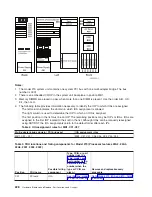


Note:
The
4758-023
card
contains
four
batteries,
even
though
only
two
batteries
are
shown
in
the
figure
above.
Battery
3
is
directly
above
Battery
1,
and
Battery
4
is
directly
above
Battery
2.
Attention:
The
loss
of
battery
power
erases
data
stored
in
the
card’s
protected
memory
and
renders
the
card
useless.
3.
Remove
the
battery
from
each
battery
holder
in
sequential
order,
starting
with
Battery
1
and
finishing
with
Battery
4.
4.
The
PCI
Cryptographic
Coprocessor
card
has
been
disabled.
You
can
now
install
the
new
card.
This
ends
the
procedure.
Tape
cartridge
-
manual
removal
For
use
by
authorized
service
providers.
Type
6335
-
1/4
inch
tape
cartridge
Type
6383,
6384,
6385,
6386,
6387
-
Tape
cartridges
Type
4685
-
Tape
cartridge
For
use
by
authorized
service
providers.
Use
this
procedure
to
remove
a
tape
cartridge
manually
from
a
4685
tape
unit.
This
procedure
may
be
required
if
a
defective
tape
cartridge
or
tape
unit
has
caused
the
cartridge
ejection
function
to
fail,
or
if
the
data
on
the
tape
cartridge
is
either
critical
or
sensitive
and
the
customer
can
not
afford
its
loss.
Attention:
This
procedure
is
very
delicate
and
may
damage
or
destroy
the
tape
cartridge.
Use
this
procedure
only
when
you
are
not
able
to
unload
the
cartridge
by
pressing
and
holding
the
unload
button.
1.
Remove
the
4685
tape
drive
tray
from
the
frame.
See
the
Removable
media
procedure
for
the
Model
you
are
working
on
in
the
2.
Remove
the
4685
tape
drive
from
the
tray.
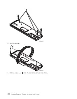
3.
Remove
the
front
bezel
(the
bezel
snaps
on)
by
doing
the
following:
a.
Use
a
small
screwdriver
to
press
the
bezel
tabs
(see
1
in
Figure
1
(See
page
on
each
side
of
the
drive.
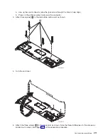
b.
Rotate
the
bottom
of
the
bezel
toward
the
front
to
release
the
bezel
attachments
on
the
top
of
the
drive.
c.
Lift
the
bezel
off
the
top
locating
tabs.
d.
Remove
the
bezel
from
the
unit.
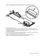
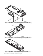
Figure
1.
Remove
the
bezel
and
top
cover
from
the
drive.
218
Hardware
(Remove
and
Replace;
Part
Locations
and
Listings)
Summary of Contents for 270
Page 2: ......
Page 12: ...x Hardware Remove and Replace Part Locations and Listings...
Page 279: ...Figure 3 CCIN 2881 with pluggable DIMM Analyze hardware problems 267...
Page 281: ...Figure 6 Models 830 SB2 with FC 9074 HSL and SPCN locations Analyze hardware problems 269...
Page 283: ...Figure 1b Model 840 SB3 processor tower dual line cord Analyze hardware problems 271...
Page 294: ...01 gif port and LED locations 282 Hardware Remove and Replace Part Locations and Listings...
Page 295: ...s src rzaq4519 gif locations Analyze hardware problems 283...
Page 483: ...Table 1 Cover assembly FC 5095 Expansion I O Tower Analyze hardware problems 471...
Page 614: ...602 Hardware Remove and Replace Part Locations and Listings...
Page 618: ...606 Hardware Remove and Replace Part Locations and Listings...
Page 621: ......
Page 622: ...Printed in USA SY44 5917 02...


