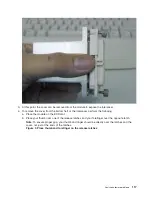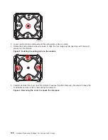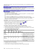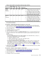
v
No:
Reinstall
the
L3
cache
module
and
go
to
L3
cache
testing,
procedure
2
(See
page
v
Yes:
Reject
the
L3
cache
module,
and
install
another
L3
cache
module.
Then,
go
to
L3
cache
testing,
procedure
2
(See
page
L3
cache
shorts
test,
procedure
5
Do
MCM
modules
need
to
be
installed?
v
Yes:
Follow
MCM
installation
shorts
test,
procedure
2
(See
page
v
No:
Remove
the
meter
and
test
card,
and
return
to
the
procedure
that
sent
you
here.
This
ends
the
procedure.
Models
870
and
890
-
System
clock
card
For
use
by
authorized
service
providers.
Use
this
procedure
to
remove
or
replace
the
System
clock
card
on
the
Models
870
and
890.
To
remove
the
system
clock
card:
1.
Power
off
the
system.
See
2.
Remove
the
MSA
(air
mover)
enclosure.
See
3.
Squeeze
the
tabs
on
the
clock
card
and
pull
it
straight
out.
4.
Perform
a
general
cleaning
operation
using
a
sash
brush
(part
number
450732)
and
vacuum
cleaner
to
remove
any
accumulated
dust
and
debris
that
has
settled
in
the
processor
subsystem.
Hold
the
vacuum
hose
near
the
brush
to
remove
any
debris
the
brush
generates.
To
replace
the
system
clock
card:
Note:
Be
sure
to
align
the
guide
feature
on
the
card
with
the
guide
feature
on
the
system
board.
1.
Squeeze
the
tabs
on
the
clock
card
and
push
it
straight
in.
2.
Replace
the
MSA
(air
mover)
enclosure.
See
3.
Power
on
the
system.
See
This
ends
the
procedure.
Models
870
and
890
-
System
unit
backplane
(MB1)
For
use
by
authorized
service
providers.
Use
this
procedure
to
remove
or
replace
the
system
unit
backplane
-
MB1
on
the
Models
870
and
890.
CAUTION:
This
unit
weighs
more
than
55
kg
(121.2
pounds).
Material
handling
systems
such
as
levers,
slings,
or
lifts
are
required
to
safely
move
it.
When
this
is
not
possible,
specially
trained
persons
or
services
(such
as
riggers
or
movers)
must
be
used.
To
remove
the
system
unit
backplane
-
MB1:
Attention:
All
components
must
be
replaced
to
the
location
from
which
they
were
removed!
Before
replacing
the
system
unit
backplane,
check
with
your
support
center
to
ensure
you
have
been
directed
to
replace
the
backplane
by
a
valid
error
code.
Attention:
This
procedure
requires
the
following:
v
A
safe
area
reserved
to
store
parts
that
are
removed
from
the
system
during
this
procedure.
v
The
use
of
a
lift
tool,
PN
09P2481
(see
the
Analyze
hardware
problems
131
Summary of Contents for 270
Page 2: ......
Page 12: ...x Hardware Remove and Replace Part Locations and Listings...
Page 279: ...Figure 3 CCIN 2881 with pluggable DIMM Analyze hardware problems 267...
Page 281: ...Figure 6 Models 830 SB2 with FC 9074 HSL and SPCN locations Analyze hardware problems 269...
Page 283: ...Figure 1b Model 840 SB3 processor tower dual line cord Analyze hardware problems 271...
Page 294: ...01 gif port and LED locations 282 Hardware Remove and Replace Part Locations and Listings...
Page 295: ...s src rzaq4519 gif locations Analyze hardware problems 283...
Page 483: ...Table 1 Cover assembly FC 5095 Expansion I O Tower Analyze hardware problems 471...
Page 614: ...602 Hardware Remove and Replace Part Locations and Listings...
Page 618: ...606 Hardware Remove and Replace Part Locations and Listings...
Page 621: ......
Page 622: ...Printed in USA SY44 5917 02...

