About the unit
Familiarize yourself with the features of the Network Active Bypass unit before you add the unit to your
network.
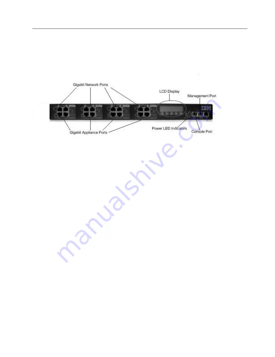
Front panel diagram
The following figure illustrates the front panel of the Network Active Bypass unit.
Note:
Segments are arranged right-to-left, in the following order: Segment 4, Segment 3, Segment 2,
Segment 1.
1.
Network ports: 1G (SR, LR, or Copper) N1 and N2 ports connecting to an Ingress network and Egress
network
2.
Appliance ports: 1G (SR, LR, or Copper) A1 and A2 ports connecting to an IPS appliance
3.
LCD display
Note:
LCD buttons are not active.
4.
LED indicators (position of LED indicators varies depending on the model)
v
Link/Active LEDs for 1G ports: lights indicate if a connection exists and the general amount of
traffic
v
Existing connection
– Green indicates a connection
– Amber indicates a collision
– No light indicates no connection
v
Amount of traffic
– Rapid blinking indicates heavy traffic
– Slow blinking indicates light traffic
– No blinking indicates no traffic
5.
Console port serial
6.
Management port Ethernet
7.
Tap port
Power adapter
You must use a UL-listed power supply with a rated output of 12 VDC, 5 A, marked LPS or NEC Class
2.
Chapter 1. Introducing the Network Active Bypass unit
3
Summary of Contents for 1G
Page 1: ...IBM Security 1G Network Active Bypass User Guide ...
Page 4: ...iv 1G Network Active Bypass User Guide ...
Page 6: ...vi 1G Network Active Bypass User Guide ...
Page 16: ...xvi 1G Network Active Bypass User Guide ...
Page 28: ...10 1G Network Active Bypass User Guide ...
Page 46: ...28 1G Network Active Bypass User Guide ...
Page 50: ...32 1G Network Active Bypass User Guide ...
Page 51: ......
Page 52: ... Printed in USA ...


