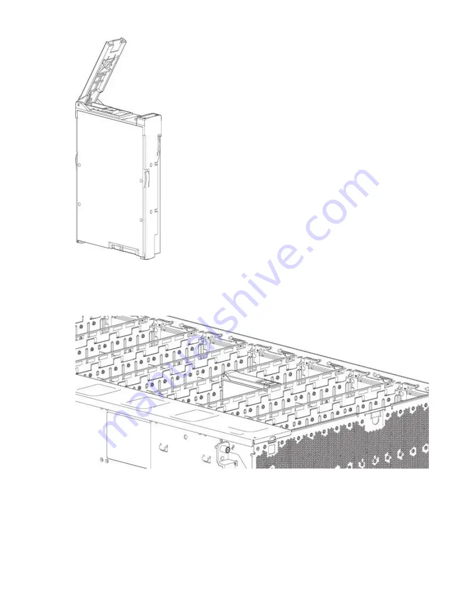
Figure 71. LFF drive carrier module in open position
2. Insert the drive carrier module into the enclosure. Make sure that the drive carrier is positioned such
that the front face of the disk is facing up, and the handle opens from the left as you face the enclosure
top panel. The module should be revolved such that its horizontal axis is parallel to the chassis
longitudinal axis, as shown.
Figure 72. Installing a LFF drive carrier module (1 of 2)
3. Slide the drive carrier fully into the disk slot within the enclosure.
4. Continue to push firmly until the handle fully engages. The camming foot on the carrier will engage into
a slot in the enclosure. You should hear a click as the latch handle engages and holds the handle
closed.
Chapter 7. Module removal and replacement 77
Summary of Contents for 106
Page 6: ...Russia Electromagnetic Interference Class A Statement 100 Homologation statement 100 vi...
Page 12: ...xii...
Page 18: ...xviii IBM ESS expansion Hardware Installation and Maintenance Guide Model 106...
Page 20: ...2 IBM ESS expansion Hardware Installation and Maintenance Guide Model 106...
Page 44: ...26 IBM ESS expansion Hardware Installation and Maintenance Guide Model 106...
Page 84: ...66 IBM ESS expansion Hardware Installation and Maintenance Guide Model 106...
Page 100: ...82 IBM ESS expansion Hardware Installation and Maintenance Guide Model 106...
Page 108: ...90 IBM ESS expansion Hardware Installation and Maintenance Guide Model 106...
Page 119: ......
Page 120: ...IBM SC27921101...


