


4. Connect the switch or circuit to the remote emergency power-off connector on
the rear of the uninterruptible power supply using insulated size 18 - 20 AWG
(0.75 mm
2
- 0.5 mm
2
) wire.
Note:
A separate contact must simultaneously cause uninterruptible power
supply input ac power to be removed.
5. Make sure that the externally connected remote emergency power-off switch is
not activated. An activated remote emergency power-off switch disables power
to the uninterruptible power supply receptacles.
Uninterruptible power supply initial startup
To start the uninterruptible power supply for the first time, complete the following
steps:
1. Make sure that the internal batteries are connected (see “Connecting the
internal battery” on page 12).
2. Make sure that the power input to the uninterruptible power supply has
adequate upstream overcurrent protection (see the following table).
Table 4. Maximum circuit breaker rating
Uninterruptible
power supply
output power
100 V
120 V
230 V
750 W
20 A
20 A
20 A
1000 W
20 A
20 A
20 A
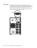
3. Connect the detachable uninterruptible power supply power cord to the input
connector on the uninterruptible power supply rear panel.
4. Connect the uninterruptible power supply power cord to a power outlet. The
uninterruptible power supply front panel display is lit. The IBM startup screen
changes to the uninterruptible power supply status summary screen. Standby
status is displayed on the front panel of the uninterruptible power supply.
5. Press the on/off button on the uninterruptible power supply front panel.
After the startup is complete, the status changes according to the
uninterruptible power supply operating mode.
6. Press the down (
) button to check for active alarms or notices. Resolve any
active alarms before you continue. For more information, see Chapter 6,
“Troubleshooting,” on page 41.
If there are no active alarms, the message
No Active Alarms
is displayed.
7. To set the date and time and to change other factory-set defaults, see
Chapter 3, “Operating the uninterruptible power supply,” on page 19.
8. If you installed an optional remote emergency power-off switch, make sure that
the function is working correctly by performing the following tests:
v
Activate the external remote emergency power-off switch. Make sure that
the status changes on the uninterruptible power supply are displayed.
v
Deactivate the external remote emergency power-off switch and restart the
uninterruptible power supply.
9. Charge the batteries. The internal batteries charge to 90% capacity in less
than 4 hours. However, you must charge the batteries for 48 hours after
installation or long-term storage.
Chapter 2. Installing the uninterruptible power supply
17
Summary of Contents for 1000VA
Page 1: ...1000 VA LCD Tower UPS and 1500 VA LCD Tower UPS Installation and Maintenance Guide...
Page 2: ......
Page 3: ...1000 VA LCD Tower UPS and 1500 VA LCD Tower UPS Installation and Maintenance Guide...
Page 50: ...40 1000 VA and 1500 VA LCD Tower UPS Installation and Maintenance Guide...
Page 67: ......
Page 68: ...Part Number 60Y1421 Printed in USA 1P P N 60Y1421...


