AST1257-940
Page
17
5. Apply downward hand pressure on the valve and
remove the locking bar, Figure 16.
6. Using the rocking motion, lift the valve from the
tank adaptor, Figure 16. If the o-ring seals come
off with the valve put them back into the tank
adaptor sockets. Lubricate the o-rings with
silicone lubricant.
Note:
Petroleum based lubricants will damage
the
Plastic valve and o-rings.
Reverse the procedure to replace the valves.
Preventative Maintenance
Injector Screen and Injector
The injector is the component which creates the
vacuum necessary to draw the brine into the water
conditioner. Clean the injector and injector screen at
least once a year in order to maintain proper
operation of the conditioner. Some locations may
require more frequent injector and screen servicing.
Refer to Figure 17 and complete the following steps
to clean the injector screen and injector:
1. Unplug the power cord.
2. Shut off the water supply or put the bypass-
valve(s) into the bypass position and remove the
rear cover, Figure 10.
3. Relieve system pressure by opening the rinse
drain valve (the fifth valve back from the control)
with a screwdriver, Figure 11.
4. Using a blade screwdriver, unscrew and remove
the injector screen and injector cap.
5. Clean screen with a fine brush. Flush with water
until clean.
6. Using a needle-nose pliers, pull the injector
straight out.
7. Flush water into the injector screen recess of the
valve body to flush debris out through the injector
recess.
8. Clean and flush the injector. Lubricate the o-rings
on the injector, injector cap and injector screen
with silicone lubricant.
9. Reinstall the injector (small and first), injector cap
and injector screen.
Figure 15
Figure 16
Figure 17
Caution
Do not overtighten the plastic cap. Seat he
cap lightly into position. Overtightening can
cause breakage of the plastic cap which may
not be evident immediately
Summary of Contents for AST1257-940
Page 20: ...AST1257 940 Page 20 Control Valving Identification Valve Disc Operation...
Page 21: ...AST1257 940 Page 21 Flow Diagrams...
Page 22: ...AST1257 940 Page 22...
Page 24: ...AST1257 940 Page 24...
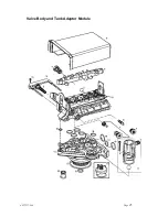
Page 25: ...AST1257 940 Page 25 Valve Body and Tank Adaptor Module...
Page 29: ...AST1257 940 Page 29...


