IBC control F21037601 Manual Download Page 7

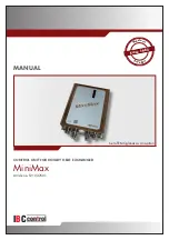
• MiniMax (enclosed IP54) is a modern, vector modulated frequency converter, with the 

additional functions necessary for optimum control of rotary heat exchangers.  

The control unit can handle all input signals currently used in the market.

• Heat exchanger rpm and thus thermal efficiency are governed by the control unit so that 

rotor speed is proportional to the input signal from the control centre.

• If the input signal is less than the set threshold value the rotor is stopped.

• When the rotor has been at a standstill for


1/2 hour,


cleaning begins and the rotor turns 

for 10 seconds at minimum rpm.

• MiniMax has an adjustable threshold of 20% of the input signal´s maximum value.

• MiniMax has adjustable boost function.

• The rotation monitor (a magnet fitted to the rotor with an associated magnetic sensor) 

stops the converter and generates an alarm in the case of a broken belt or similar.

• In the event of over- or under voltage on the mains, short circuit or earth fault and 

tripped thermal contact in the motor, the control unit trips and generates an alarm.

• MiniMax starts automatically after voltage drop-out,  

and resets all alarms on restart.

• The motor should not be disconnected from the control unit while under load.

• The control unit can be equipped with extra cards. The following cards are available: 

 - Differential temperature regulator with electrical heating output 

 - 2-rotor module

DESCRIPTION OF FUNCTIONS

4

5

Summary of Contents for F21037601

Page 1: ...IBCcontrol MANUAL CONTROL UNIT FOR ROTARY HEAT EXCHANGER MiniMax Article no F21037601 Set of EMC glands as an option M ade in S w ed en Since 1983 Since 1983 Ska vara 25 mm i diameter p h jden...

Page 2: ......

Page 3: ...functions 5 Technical data 6 Functions 6 DIP switch 7 Operational indications 8 Alarms 8 9 Settings via potentiometer 10 Reset 10 Connection diagram 11 Connections 11 12 Checks before powering up the...

Page 4: ...Disposal and recycling When replacing components or when the control unit in its entirety need replacing please follow the advice below The aim should always be maximum possible recycling of raw mate...

Page 5: ...power before removing the cover Never touch electrical components or contacts while main current is switched on Risk of electric shock resulting in serious injury or death Connected terminals contain...

Page 6: ...The Electromagnetic Compatibility Regulations 2016 The Electrical Equipment Safety Regulations 2016 The Restriction of the Use of Certain Hazardous Substances in Electrical and Electronic Equipment Re...

Page 7: ...has an adjustable threshold of 20 of the input signal s maximum value MiniMax has adjustable boost function The rotation monitor a magnet fitted to the rotor with an associated magnetic sensor stops...

Page 8: ...0 60 Hz Power input max 650 W Input current max 2 8 A External fuse max 10 A Output voltage 3x0 230 V Min frequency 5 20 Hz Max frequency 40 100 Hz Motor output max 370 W Motor current max 1 9 A Exact...

Page 9: ...4 20 mA 0 0 1 0 1 0 Cleaning function 1 Cleaning function connected in ON position When the rotor has stopped for 30 minutes the cleaning function is activated and the rotor rotates at minimum speed...

Page 10: ...every 5 minutes Magnet turned the wrong way Rotation monitor incorrectly connected refer to Connections on pages 11 12 Too wide a gap between the magnetic sensor and magnet max 15 mm Broken belt Belt...

Page 11: ...e motor resistance it should be identical on all phases Short circuit between phases in the cable Earth fault in the motor or cable Overcurrent MiniMax limits thr current at 4 A and trips then after 4...

Page 12: ...eased if necessary but motor temperature will increase Acc Acceleration time 0 30 s Factory set to max does not need adjustment Ret Retardation time 0 30 s Factory set to max does not need adjustment...

Page 13: ...tion monitor A1 A2 A3 1 2 6 10 12 w S br Manual high low speed Input signal Run 3 5 9 11 Reset 1 2 3 Pot 10 k Potentiometer input L N V W 1 x 230 V U Max 2 A 250 V AC 3 x 230 V Max 370 W 13 14 15 T T...

Page 14: ...Remote reset in the event of alarm connection between terminals 11 12 The control unit is reset automatically in the event of voltage drop out See also Reset page 10 Control relay 16 17 Closes circui...

Page 15: ...e voltage Make sure the cleaning DIP switch is set to ON and the input signal is disconnected When power is switched on the rotor will rotate at minimum rpm for 10 seconds Checking the rotation monito...

Page 16: ...GLAND Motor Connection voltage 3G1 5 Not shielded lflex Classic 110 CY 7G0 5 Shielded EMC glands must be used for shielded cables The above cables or equivalent must be used to comply with the EMC Dir...

Page 17: ...PERSONAL NOTES 15...

Page 18: ...16 PERSONAL NOTES...

Page 19: ...17 PERSONAL NOTES...

Page 20: ...IBC control AB Br nnerigatan 5 A 263 37 H gan s Sverige Tel 46 42 33 00 10 www ibccontrol se info ibccontrol se IBCcontrol F21037906GB Version 1 0 1 2021 10 01...

Reviews: