background image

FWA6504 

User’s Manual 


The Jumpers 


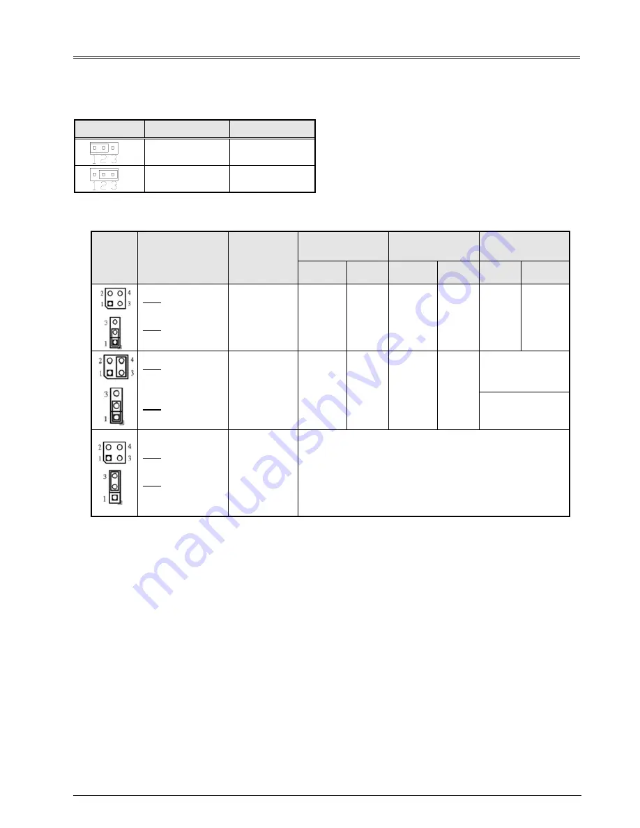
JP1: Clear CMOS Contents 

Use JP1 to clear the CMOS contents.  

Note that the power connector or jack should be disconnected from the board before clearing CMOS. 


JP1 

Setting 

Function 


Pin 1-2 

Short/Closed 

Normal 


Pin 2-3 

Short/Closed 

Clear CMOS 


JP4, JP5: LAN Bypass & WDT Reboot Setting 

JP4 

JP5 

Setting 

Function 

Power 

OFF 

Power 

ON 

Power ON 

OS run software 

Normal  Bypass  Normal  Bypass Normal  Bypass 


JP4 
1-2 & 3-4 Open 

JP5 
1-2 Closed 

LAN bypass 
upon the 
time out of 
WDT. 


JP4  
3-4 Closed  
1-2 Open 

JP5  
1-2 Closed 

LAN bypass 
& system 
reboot upon 
the time out 
of WDT. 


LAN Always 
Normal 

WDT Reboot 
System 


JP4 
1-2 & 3-4 Open 

JP5 
2-3 Closed 

LAN bypass 
controlled 
by Super IO 
GP54 or 
setting in 
BIOS. 

BIOS Setting ** 
GP54 Active: 
Low: Bypass 
High: Normal 


** Note that the Bypass setting in BIOS is only working when JP4 & JP5 are set as this configuration. 


De
fa

u

lt 

 Se

tt

in


Summary of Contents for FWA6504

Page 1: ...FWA6504 1U 19 Network Appliance User s Manual Version 1 0...

Page 2: ...tem Specification 5 Chapter 3 Hardware Configuration 6 Chapter 4 Console Mode Information 11 Chapter 5 Opening the Chassis 13 Chapter 6 Installing CompactFlash Card 13 Chapter 7 Installing Memory Modu...

Page 3: ...product on an unstable cart stand or table The product may fall causing serious damage to the product Slots and openings on the chassis are for ventilation Do not block or cover these openings Make su...

Page 4: ...turer s instructions may cause harmful interference to radio communications However there is no guarantee that interference will not occur in a particular installation If this equipment does cause har...

Page 5: ...Network Management Applications Load balancing Quality of Service Remote Access Service The FWA network appliance product line covers the spectrum from offering platforms designed for SOHO SMB Enterp...

Page 6: ...U on die memory controller supporting up to 4GB One DDR3 1066 SO DIMM socket Non ECC unbuffered 1 5V LAN Console RS 232 RJ45 Eth1 2 3 4 Intel 82583V RJ45 with LED Network Bypass One segment hardware B...

Page 7: ...FWA6504 User s Manual 6 Chapter 3 Hardware Configuration Motherboard MB837 1U Layout...

Page 8: ...ion Power OFF Power ON Power ON OS run software Normal Bypass Normal Bypass Normal Bypass JP4 1 2 3 4 Open JP5 1 2 Closed LAN bypass upon the time out of WDT JP4 3 4 Closed 1 2 Open JP5 1 2 Closed LAN...

Page 9: ...d 2 DTR Data terminal ready 3 TXD Transmit data 4 Ground 5 Ground 6 RXD Receive data 7 DSR Data set ready 8 CTS Clear to send CN7 SATA SSD Dock The SATA SSD dock combines a SATA power connector and a...

Page 10: ...ash Connector J8 COM2 Serial Port Pin Signal Name RS 232 1 DCD Data carrier detect 2 RXD Receive data 3 TXD Transmit data 4 DTR Data terminal ready 5 Ground 6 DSR Data set ready 7 RTS Request to send...

Page 11: ...in Header Signal Name Pin Pin Signal Name PWR LED A1 C1 PWR LED ALARM LED A2 C2 SIO GPIO55 STATUS LED A3 C3 SIO GPIO56 SW3 Software Reset Button Signal Name Pin Pin Signal Name GND 1 2 PCH GPIO7 Note...

Page 12: ...loaded with an existing OS such Windows XP Connect client computer and FWA6504 with NULL Modem cable Follow the steps below to configure the Windows Hyper Terminal application setting 1 For executing...

Page 13: ...t settings to Baud rate 115200 Parity None Data bits 8 Stop bits 1 5 Power up FWA6504 and the screen will display the BIOS information 6 Press Tab key to enter BIOS setup screen in Console mode Press...

Page 14: ...t and right sides Fig 5 2 The system Chapter 6 Installing CompactFlash Card Fig 6 1 Insert Compact Flash Card Fig 6 2 Push Compact Flash Card into the CF interface Chapter 7 Installing Memory Module F...

Page 15: ...nstalling 2 5 SSD Fig 8 1 Loosen two screws to remove left right side brackets Fig 8 2 Fasten brackets on SSD with four screws Fig 8 3 Fasten both brackets on SSD with four screws Fig 8 4 Fix SSD brac...

Page 16: ...6504 User s Manual 15 Chapter 9 Installing Mini PCI e Module Fig 9 1 Insert Mini PCI e module Supports USB signal only Fig 9 3 Release two clips to remove module Fig 9 2 Push down the module into sock...

Reviews: