

TECHNICAL DATA
Minimum dynamic pressure:
0.5 bar
Maximum operational pressure:
10 bar
Recommended operational pressure:
1-5 bar
It is recommended to use a pressure reducer,
if inside the waterpipes there are static pressure superior to 5 bar
Maximumhot water temperature
80°C
INSTALLATION, MAINTENANCE AND PRELIMINARY CHECKING PROCEDURE
To ensure that the mixer tap unit functions correctly and lasts over time, the installation and maintenance
procedures illustrated in this leafl et must be complied with. Have all work done by a qualifi ed plumber.
Ensure that all debris and dirt have been removed from the system.
INSTALLATION
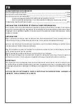
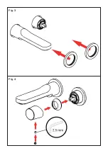
Fig 1 + Fig 3
Place the body of the mixer tap unit in the cavity provided in the wall, taking care to refer to the
MIN and MAX installation markings printed on the protective cover.
N.B.:
the MIN and MAX
markings refer to the fi nished wall, complete with tiles etc.
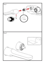
Fig 2
Remove the plastic plugs and connect to the system pipes (hot and cold water intake. Hemp
should be used to ensure watertight seals on the threads.
Fig 4
Secure the unit inside the wall, using a spirit level to position it correctly.
After connecting the body of the mixer tap unit to the system, turn on the stop taps and check that the unit
operates correctly. Check the system to be sure that there are no leaks.
Fig. 5
Wall in the tap body unit, reducing the size of the cavity so that it will be covered by the fi ni-
shing plate. Do not cover connections with cement, to allow maintenance if necessary.
WARNING:
once the wall is fi nished, check compliance with the minimum and maximum
markings on the protective cover.
CLEANING
To clean the unit correctly, use only soap and water, rinse and dry with a chamois leather or soft cloth.
Never use alcohol, solvents, solid or liquid detergents containing corrosive substances or acids, synthetic
fi bre rags, abrasive sponges or steel wire scouring pads, since they may cause irreparable damage to the
treated surfaces.
CARACTÉRISTIQUES TECHNIQUES
Pression dynamique mini.:
0.5 bar
Pression maxi. d’exercice:
10 bar
Pression d’exercice recommandée:
1-5 bar
Il est recommandé d’utiliser un réducteur de pression en cas
de pressions statiques supérieures à 5 bars dans l’installation.
Température maxi. eau chaude:
80°C
NORMES D’INSTALLATION, D’ENTRETIEN ET VÉRIFICATIONS PRÉLIMINAIRES
Pour que votre appareil fonctionne correctement et dure dans le temps, il est nécessaire de respecter les
modalités d’installation et d’entretien illustrées dans cet opuscule. Demander l’intervention d’un plombier
qualifi é. Vérifi er que l’installation est libre de tous détritus et de toutes impuretés.
INSTALLATION
Fig 1 + Fig 3
Positionner le corps du mélangeur dans le logement pratiqué dans le mur en tenant compte
des repères de pose MIN et MAX imprimés sur le carter de protection.
N.B.
les repères MIN
et MAX tiennent compte du mur fi ni, revêtement compris.
Fig 2
Retirer les bouchons en plastique et effectuer le raccordement aux conduites du réseau (entrée
eau froide et chaude). Il est conseillé d’utiliser du chanvre pour garantir l’étanchéité des fi lets.
Fig 4
Stabiliser le corps à l’intérieur du mur en s’aidant d’un niveau à bulle en vue d’un positionne-
ment correct.
Après avoir raccordé le corps à encastrer à l’installation, ouvrir les robinets et vérifi er le fonctionnement du
mélangeur. Contrôler l’absence de pertes.
Fig. 5
Murer la partie encastrée en réduisant les dimensions du logement de façon à ce que ce
dernier soit recouvert par la plaque de fi nition. Éviter de recouvrir les raccords de ciment
en vue des opérations d’entretien éventuelles.
ATTENTION:
une fois le mur fi ni, vérifi er
que les dimensions min. et max. d’encastrement indiquées sur le carte de protection ont été
respectées.
NETTOYAGE
Pour un nettoyage correct, laver exclusivement à l’eau savonneuse, rincer et essuyer avec une peau de
chamois ou un chiffon doux. Éviter l’emploi d’alcool, solvants, produits détergents solides ou liquides conte-
nant des substances corrosives ou acides, les chiffons synthétiques, les éponges abrasives et les pailles de
fer, étant donné qu’ils peuvent endommager irrémédiablement les surfaces traitées.
DATI TECNICI
Pressione dinamica Min:
0.5 bar
Pressione Max di esercizio:
10 bar
Pressione di esercizio raccomandata:
1-5 bar
Si raccomanda di utilizzare un riduttore di pressione,
se all’interno dell’impianto si hanno pressioni statiche superiori a 5 bar.
Temperatura Max acqua calda:
80°C
NORME DI INSTALLAZIONE, MANUTENZIONE E VERIFICHE PRELIMINARI
Perché il suo apparecchio funzioni nella maniera corretta e possa durare nel tempo, occorre che vengano
rispettate le modalità di installazione e manutenzione illustrate in questo opuscolo. Affi darsi ad un idraulico
qualifi cato. Assicurarsi che l’impianto sia stato liberato da tutti i detriti e impurità esistenti.
INSTALLAZIONE
Fig 1 + Fig 3
Posizionare il corpo miscelatore nell’alloggiamento realizzato nella parete, ponendo partico-
lare attenzione ai riferimenti per la posa MIN e MAX stampati sul carter di protezione.
N.B.:
i
riferimenti MIN e MAX sono intesi dalla parete fi nita, compreso il rivestimento.
Fig 2
Estrarre i tappi in plastica ed allacciarsi alle tubazioni della rete (entrata acqua fredda e calda).
È consigliabile utilizzare la canapa per garantire tenuta sui fi letti.
Fig 4
Stabilizzare il corpo all’interno della parete individuando, con l’ausilio di una livella a bolla
d’aria, il corretto posizionamento.
Dopo aver collegato il corpo incasso all’impianto, aprire i rubinetti d’arresto e verifi care il corretto funziona-
mento del miscelatore. Controllare la mancanza di perdite nell’impianto.
Fig. 5
Murare l’incasso diminuendo le dimensioni dell’alloggio in modo che rimanga coperto dalla
piastra di fi nitura. Evitare di coprire gli attacchi con il cemento per eventuale manutenzione.
ATTENZIONE:
verifi care a parete fi nita di rientrare nelle misure minime e massime di in-
casso indicate sul carter di protezione.
PULIZIA
Per una corretta pulizia, lavare esclusivamente con acqua e sapone, risciacquare ed asciugare con una
pelle di daino o panno morbido. Evitare assolutamente l’impiego di alcool, solventi, detersivi solidi o liquidi
contenenti sostanze corrosive o acide, strofi nacci prodotti con fi bre sintetiche, spugne abrasive e tamponi
con fi li metallici, poiché potrebbero alterare irreversibilmente le superfi ci trattate.
Fig 1
Fig 3
Fig 2
Fig 4
Fig. 5