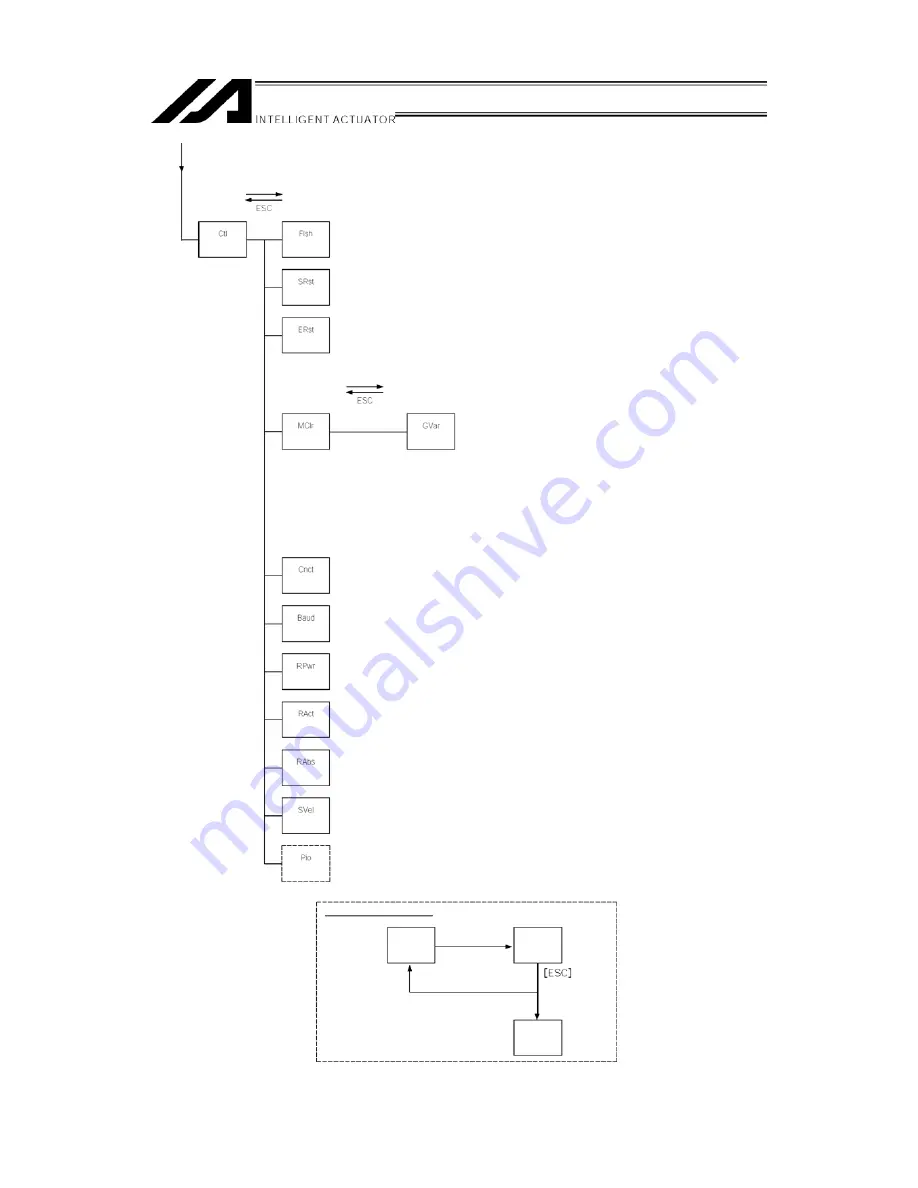
IAI X-SEL Operating Manual Download Page 18


Function key 

(Flash ROM 

writing) 

(Controller) 

(Software 

reset) 

(Error reset) 

Function key 

(Memory 

clear) 

(Global 

variable) 

(Re-connect) 

(Baud rate 

change) 

(Driver power 

recovery request) 

(Action pause 

release request) 

(Absolute 

reset) 

*  You need to input the password to change setting, when manual operation classification

parameter=edit/start up selection (with password).


(Velocity effect 

select) 

*  Displayed only when manual operation classification parameter=edit/start up selection (with

password). 

*  You will need to input the password to change setting. 
(Refer to the Supplement and section 8 “Manual Operation” in the X-SEL Controller Instruction
Manual.) 

(PIO start 

prohibit select) 

 Flow at Error Occurrence 

Error occurs 

Mode under 

operation 

Message 

display 

Serious error 

Minor error 

Re-connection 

mode 

15 

Summary of Contents for X-SEL

Page 1: ...X SEL Teaching Pendant Operating Manual Ver 7 0 IAI Corporation ...

Page 2: ...mple Operation Procedure 19 9 1 Creation of Position Data 20 9 2 Programming 29 9 3 Changing Application Program 37 10 Program Execution 42 10 1 Operation Confirmation 42 10 2 Setting of Brake Point 44 10 3 Monitor under Operation 44 11 Position Edit 47 11 1 Mdi Manual direct input 47 11 2 Teach Teaching 48 11 3 Example of Teaching Input 59 11 4 Position Data Copy or Move 64 11 5 Position Data Cle...

Page 3: ...mation 104 16 Controller 106 16 1 Controller Items 106 16 2 Flash ROM Writing 107 16 3 Software Reset 108 16 4 Error Reset 108 16 5 Memory Clear 109 16 6 Re Connection 109 16 7 Baud Rate Change 110 16 8 Safety Velocity 110 16 9 Driver Power Recovery Request 111 16 10 Action Pause Release Request 111 16 11 Driver Power Recovery Request RPwr and Action Pause Release Request Ract 112 16 12 Absolute R...

Page 4: ...ing to the program velocity command it is required to change the condition to No Effect For selection of the safety velocity between Effect and No Effect refer to 16 8 Safety Velocity When connecting this teaching pendant to the X SEL Q type global specification emergency stop cannot be reset The display screens must show version 1 13 or newer of the teaching pendant application software To confir...

Page 5: ...ead location In addition give special consideration to prevent third parties from turning on the power carelessly by hauling in the power cord to the operator Alternatively lock the power plug or receptacle and direct the operator to keep the key or prepare a safety plug 4 When more than one operator works advance work by determining the signal method and checking each other s safety Especially fo...

Page 6: ... as a cable Defects resulting from sensory phenomena such as generated noise that have no functional effects Defects resulting from mishandling or improper use Defects resulting from an inadequacy or error in maintenance and inspection Defects resulting from the use of any part other than our genuine parts Defects resulting from a modification not approved by us or our dealers Defects resulting fr...

Page 7: ...5 Connection to Controller Mode Switch M cable K J Type Controller 4 ...

Page 8: ...Emergency Stop Switch Enable Switch Teaching Pendant Type Selection Switch Mode Switch P Type Controller Set the teaching pendant type selection switch to the right Caution 5 ...

Page 9: ...e controller Teaching Pendant LCD Display Displays the version of the teaching pendant and moves to the following page the mode selection screen If the mode is switched to AUTO side the teaching pendant does not connect to the controller and the screen on the left will be displayed Press ESC key and make it reconnected Re connection Screen Mode Selection Screen Turn on the mode switch to MANU side...

Page 10: ...TP port teaching connector according to the servo not in use or in use MANU mode servo not in use Before execution of OPEN After execution of OPEN Connection of TP port Connection to Teaching Pendant Forced movement to SEL program connection Message error Program is executing Error occurring after OPEN command execution Error No A50 SCIF open error during non AUTO mode MANU mode servo in use Befor...

Page 11: ...utes emergency stop 3 Deadman Switch Option Before operating keys for Servo OFF Servo ON keep pressing both sides ON and operating keys If you press only one side or not press both sides key operation for Servo OFF Servo ON doesn t work When servo is ON this switch is under the state of both side pressed but when you release the switch the operation will be finished and the panel window 7 seg LED ...

Page 12: ...mitted all together at the same time 7 ESC key Escape key Returns to the previous status from the current status If you press this key during data input the data will be cancelled 8 BS key Backspace key If you press this key during data input clear one letter before At other time clear the data where the cursor is placed 9 key Cursor backward key Backward the cursor It s reverse of Return key func...

Page 13: ...nd 5th axis 1 Plus direction jog movement for the 1st axis and 5th axis 2 Minus direction jog movement for the 2nd axis and 6th axis 2 Plus direction jog movement for the 2nd axis and 6th axis It s valid in the Teac teach mode area with the servo ON 3 Minus direction jog movement for the 3rd axis 3 Plus direction jog movement for the 3rd axis 4 Minus direction jog movement for the 4th axis 4 Plus ...

Page 14: ...s movement Jog velocity Output monitor Velocity data Input monitor Cancel Data import Display change Clear Data import Display change Cursor position data Cursor position No Velocity input Function key Copy Move Clear Teach Select position No and press return Function key Write to Flash ROM Yes or No When escaping the mode with ESC check whether to write to Flash ROM After writing data with WRT mo...

Page 15: ... next edit No Select the parameter type with the function key Parameter input Parameter After writing data with WRT move to the next edit No Select the program No and press return Function key Function key Move to the mode according to the current condition Program operation Current position Continuous execution Step execution Execution Step execution completed Local flag Function key Execution st...

Page 16: ...Input port Output port Global flag Function key Global variable Integer variable Real variable String variable Function key Current position Axis status Servo status Sensor input status Encoder status Axis related error 13 ...

Page 17: ...s System mode System error System status 1 System status 2 System status 3 System status 4 Error list Function key Version CTL main Driver Teaching pendant P Q type only Mount SIO P Q type only P Q type only Control constant 14 ...

Page 18: ...classification parameter edit start up selection with password Velocity effect select Displayed only when manual operation classification parameter edit start up selection with password You will need to input the password to change setting Refer to the Supplement and section 8 Manual Operation in the X SEL Controller Instruction Manual PIO start prohibit select Flow at Error Occurrence Error occur...

Page 19: ...arameter No 20 2 System memory backup battery equipped Edit data with PC or Teaching Pendant Save the data during the power is on and delete the data by reset Save data even after the power OFF Flash write Program parameter content 1 Symbol Flash memory Memory Transmit Reset read Transmit Slave card parameter content 2 Memory Transmit Reset read Transmit Encoder parameter Memory Encoder Transmit R...

Page 20: ...ped Edit data with PC or Teaching Pendant Save the data during the power is on and delete the data by reset Save data even after the power OFF Program Parameter content 1 Symbol Position Flash write Flash memory Memory Transmit Reset read Transmit Slave card parameter content 2 Memory Transmit Reset read Transfer Encoder parameter Encoder Transmit Memory Reset read SEL global data content 3 Error ...

Page 21: ...roller which has been powered on or of which software has been reset when the actuator encoder is not connected in a file the encoder parameters stored in this file become invalid values Cautions in transferring a parameter file to controller When the parameter file is transferred to the controller the encoder parameters are transferred to EEPROM of the encoder excluding manufacturing information ...

Page 22: ... Operation Procedure Here the program and position data to draw a simple pentagon passing through the following 6 points and are same position by the actuator of 2 axes X Y are created Home Position Data to 19 ...

Page 23: ... MANU side Supply the power to the controller Display the version of the teaching pendant and move to the mode selection screen to the following page If the MODE switch is AUTO side the teaching pendant does not connect to the controller and display as the screen on the left Press ESC key to make it re connection display Turn on MODE switch to MANU side and press F1 Yes key to re connect 20 ...

Page 24: ...s the F1 key Edit If you make a wrong selection or input press the ESC key and return to the previous screen Then you can continue operation You can return to the basic screen by pressing the ESC key several times from any screen Edit Mode Screen Press the F1 key Posi 21 ...

Page 25: ...original data is gone or use the PAGE UP PAGE DOWN keys to be placed at x xxx and then input the data Clear all axis input data by pressing the F1 Clr key twice You can clear the controller data with Clr key even if the WRT key is not pressed When input the 5th and 6th axes data press the F4 Axis key to switch the display to the 5th and 6th axes data display screen The F4 Axis key is used to switc...

Page 26: ...ond axis position data and press return key Every press of return key the cursor position moves When you miss input place the cursor to the miss input position and write over Also you can return the input data to x xxx with the F3 Canc key Transmit the data with the WRT key position No forwards 1 and becomes 2 If you change the screen with the PAGE UP PAGE DOWN or ESC keys before transmitting the ...

Page 27: ...ansmit the data with the WRT key and move to position No 3 Data input for the third point Input 100 for the first axis position data and press the return key Input 50 for the second axis position data and press return key Transmit the data with the WRT key and move to position No 4 24 ...

Page 28: ...rn key Input 0 for the second position data and press the return key Transmit the data with the WRT key and move to position No 5 Data input for the fifth point Input 0 for the first axis position data and press the return key Input 0 for the second axis position data and press the return key 25 ...

Page 29: ...t 0 for the first axis position data and press the return key Input 50 for the second axis position data and press the return key Transmit the data with the WRT key and move to position No 7 Finish editing then write the data to Flash ROM The cursor moves to the position No by pressing ESC key 26 ...

Page 30: ... pressing the ESC key once more The Flash ROM writing screen will be appear by pressing the ESC key again To write the data to Flash ROM press the F1 Yes key If not press the F2 No key During Flash ROM writing Please Wait blinks Never shut off the power to the controller during Flash ROM writing 27 ...

Page 31: ...Go back to the edit screen by pressing the ESC key That s all for inputting basic position data 28 ...

Page 32: ...nd For restart after homing temporary stop execute it from the beginning of the homing sequence The homing operation of the ABS encoder axis becomes the movement to the multi rotation data reset position When operation is reset during its execution in a mode other than the absolute reset mode of the PC compatible software Teaching Pendant the real position soft limit error may occur depending on t...

Page 33: ...he program No Move the cursor to the step No with return key If the program data is already input write over the data will be gone or select the program No which has no program data The cursor location on program No or step No can be changed with PAGE UP PAGE DOWN keys Also you can change the program No and step No by pressing the return key after the 10 key input Program No Step No The number of ...

Page 34: ...ea each time by pressing the 10 key Display the command you d like to input in the function key area with the steps of and above and press the corresponding function key How to search the command HOME The commands which start with G H or I will be displayed by pressing the 9 key of the 10 keys Some commands can t be displayed by pressing one of the 10 keys In this case press the SF shift key and o...

Page 35: ... over or delete with BS backspace key Or redo from step No by using ESC key Transmit data to the controller by pressing the WRT key Step No moves to 2 If you change the screen with the PAGE UP PAGE DOWN or ESC keys before transmitting the data the input data will be invalid Press the 10 key 2 or SF shift key to search VEL Select the F3 key VEL Press the return key Step No 2 32 ...

Page 36: ...iven there Transmit the data to the controller by pressing the WRT key The cursor moves to step No 3 If you change the screen with the PAGE UP PAGE DOWN or ESC keys before transmitting the data the input data will be invalid By using the 5 and SF shift keys this will display the MOVL Select the F3 key MOVL Press the return key The cursor moves to operation 1 33 ...

Page 37: ... change the screen with the PAGE UP PAGE DOWN or ESC keys before transmitting the data the input data will be invalid Input MOVL 2 MOVL 6 program data into steps No 4 8 by the same procedure and transmit the data to the controller Display EXIT in the function key area by using the 8 and SF keys Select the F2 key EXIT and press the return key 34 ...

Page 38: ...ys before transmitting the data the input data will be invalid Finish editing the program and write the data to Flash ROM Press the ESC key The cursor moves to the step No Press the ESC key The cursor moves to the program No Press the ESC key Return to the program edit screen Press the ESC key Return to the edit screen 35 ...

Page 39: ...ash ROM press the F1 Yes key If not press the F2 No key During Flash ROM writing Please Wait blinks Never shut off the power to the controller during Flash ROM writing Flash ROM writing is complete Return to the edit screen with the ESC key 36 ...

Page 40: ...ert and delete the program step to allow the same action to be repeated Change Insert TAG 1 into step No 3 delete the line which displays MOVL 6 and write over GOTO 1 replacing it with EXIT Select the F1 key Edit on the mode selection screen Press the F2 key Prog on the program mode screen 37 ...

Page 41: ...en Press the return key once and position the cursor at the step No Insert a 1 line step between step No 2 and 3 Input 3 by pressing 3 or display 3 by pressing the PAGE UP key twice Select the F1 key Ins I Insert of I will be displayed after step No 3 Display TAG by using the 1 key or the SF shift key 38 ...

Page 42: ...hange the screen with the PAGE UP PAGE DOWN or ESC keys before transmitting the data the input data will be invalid Display the step No 4 screen by pressing the ESC key twice Delete the MOVL 6 Input 9 for the step No by pressing the 9 key directly to the same cursor location or display the MOVL 6 by pressing PAGE UP key 5 times The cursor is located at step No 9 39 ...

Page 43: ...2 key Del Press the F2 key Del one more time If you wish to cancel deleting press the ESC key Press the return key Display GOTO by using the 9 key or SF shift key Select the F3 key GOTO and press the return key 40 ...

Page 44: ...WN or ESC keys before transmitting the data the input data will be invalid Press the ESC key several times and move to the Flash ROM writing screen To write the data to Flash ROM press the F1 Yes key If not press the F2 No key During Flash ROM writing Please Wait blinks Never shut off the power to the controller during Flash ROM writing Flash ROM writing is complete Return to the edit screen with ...

Page 45: ... mode screen F1 Run Move to the program No input screen to execute F2 TSts Move to the task status screen which is already executing F3 AStop Finish all programs which are executing F2 and F3 keys are function keys which are used after executing programs Finish all programs The cursor is located at the program No Input the program No you d like to execute with the PAGE UP PAGE DOWN keys and press ...

Page 46: ...ting program step display the next step Execute programs step by step each time you press the F2 Step key Switch to continuance operation by pressing the F1 Cont key Select the finish operation by pressing the F3 Stop key The monitor under operation F1 Posi Display Current Position F2 LFlg Local Flag F3 LVar Local Variable The monitor under operation F1 Posi Display Current Position F2 LFlg Local ...

Page 47: ...you set After pausing press the F1 Cont key to continue executing rest of the program Or execute the step operation by pressing F2 Step key Program No Step No 10 3 Monitor under Operation The current position of the actuators and data in the local area can be monitored during continuous operation Press the SF shift key at the continuance operation mode screen or the step operation mode screen Moni...

Page 48: ...riables and the local strings Moreover values can be substituted for a local variable and the character sequence can be substituted for a local string Select the F3 LVar key on the operation mode screen 3 kinds of local variables are displayed F1 Itg Integer F2 Real Real Number F3 Str String Local Integer variable Mode Transition Local Real Variable Mode Transition The cursor is located in the dat...

Page 49: ...pressing one of 10 keys and press return key to substitute letters Convert hexadecimal A F to alphabet with the F1 Alph Num key and then input substitution Move the cursor location with the return key and key The PAGE UP PAGE DOWN keys scrolls the cursor every 20 columns each time they are pressed 46 ...

Page 50: ...Input screen Position No Return Vel is displayed at the function key area of the data input screen for each axis Press the F2 Vel key Vel ACC Dcl Input Screen Move the cursor with the return key and input the value to the required place by using the 10 keys Then press the return key After input transmit the data to the controller with the WRT key If you change the screen with the PAGE UP PAGE DOWN...

Page 51: ...axis No for data input Take the data of the current position of the actuator into the data input screen Transmit the data to the controller Input the position data by teaching and repeating Teaching is transacted mainly at the teaching screen Transition to the teaching screen Axis No displayed Position No Selection Screen Position No Number of axes of controller Switches the 1st to 4th axes displa...

Page 52: ...lear the all axis data of the selected position No by pressing this key twice Clear the controller s data without pressing the WRT key TP Ver 1 02 or later F4 Axis Switch the 1st to 4th axes display screen to the 5th and 6th axes display screen Effective for 5 axes or more F1 Cont Execute continuance operation F2 JVel Set the jog velocity F3 In Monitor the input port F4 Out Monitor the output port...

Page 53: ... axes display screen to the 5th and 6th axes display screen Effective for 5 axes or more F1 Vel Input the data of velocity to each position No F2 JVel Set the jog velocity F3 In Monitor the input port F4 Out Monitor the output port Each axis Data Input Screen F1 Cont Move to the continuance transition mode F2 UsrO Turn ON OFF the output ports sequential 8 points at the maximum set to parameters It...

Page 54: ...eaching Turn the servo On by pressing the ON OFF key in the teaching screen condition To confirm servo ON OFF status press the F1 Disp key All axes start homing by pressing the HOME key The data of the current position screen before homing doesn t have meaning After homing is complete execute teaching 51 ...

Page 55: ... 5th and 6th axes data display screen 1 Plus direction for the 5th axis 1 Minus direction for the 5th axis 2 Plus direction for the 6th axis 2 Minus direction for the 6th axis Changing the Jog Velocity Change the actuator s moving velocity at the time of the jog operation Display JVel jog velocity on the Teaching screen and press the function key that it corresponds to Depending on the screen cond...

Page 56: ...ress the key changes the jog velocity per second as follows 1 10 50 100 mm sec Manual Movement with Servo OFF Status Press the ON OFF key to turn the servo OFF To confirm the servo ON OFF status press the F1 Disp key Move the actuators to the designated position via manual mode 3 Take in the current position as a data Input the position No into which data is taken on the position No selection scre...

Page 57: ...C keys before transmitting the data the input data will be invalid 5 I O Monitor Location Confirmation During teaching operation you can monitor the input and output ports You can also confirm the location by moving an actuator to a to the location of the position data with teaching Input Output Monitor Select In or Out from the function keys in the teaching screen condition In Input port Out Outp...

Page 58: ...N To confirm the servo ON OFF status press the F1 Disp key It starts moving by pressing the MOVE key To the Stop press STOP key When you confirm or change the moving velocity press F2 JVel key to move to the velocity changing screen Input alteration data with 10 keys and press return key After changing return to the previous screen with ESC key Position No to move Moving velocity 50mm sec 55 ...

Page 59: ...data with the 10 keys and press the return key After changing return to the previous screen with the ESC key The moving velocity is set 50mm sec at the diagram on the left Continuous movement starts by pressing MOVE key During continuous movement the display changes to the current position display To stop press the STOP key To re start continuous movement press the MOVE key Note Please take note t...

Page 60: ... ON OFF condition N ON F OFF are displayed for each axis C Function for operation of user specified output ports This is the function for ON OFF operation of user specified output ports This function is allocated to Usr1 Usr2 Usr3 in this order from the first user specified port for the number of specified ports Usr1 to Usr4 and Usr5 to Usr8 are changed with the SF key ON OFF operation can be perf...

Page 61: ...t Number of output ports used by TP user hand etc First port No I O parameter No 75 Top No Use Out First output port No by TP user hand etc Setting example When the first port No is set to 308 and the number of ports is set to 8 Usr1 F1 key Output port 308 Usr2 F2 key Output port 309 Usr3 F3 key Output port 310 Usr4 F4 key Output port 311 Usr5 F1 key Output port 312 Usr6 F2 key Output port 313 Usr...

Page 62: ...tion No 11 by manual operation with Servo OFF status Select the F1 Edit key on the mode selection screen Select the F1 Posi key Select the F2 Teac key Input 10 to Position No by using the PAGE UP PAGE DOWN keys or the 10 keys and then the return key Turn the servo ON by pressing the ON OFF key 59 ...

Page 63: ... display to the data input screen with the F1 Disp key Confirm that the data has been taken in Press the return key to move the cursor to the next axis Then press the F2 Scan key Transmit position data to the controller by pressing the WRT key The Position No moves to 11 If you change the screen with the PAGE UP PAGE DOWN or ESC keys before transmitting the data the input data will be invalid 60 ...

Page 64: ... may fall by weight such as a hand attached at the tip Therefore do not execute teaching to the Z axis via manual mode Take in the current position data of the axis No where the cursor is located by pressing the F2 Scan key Press the return key and make the cursor move to the next axis Then press the F2 Scan key Transmit position data to the controller by pressing the WRT key The Position No moves...

Page 65: ...Finish the position data input by teaching Press the ESC key Press the ESC key Press the ESC key Press the ESC key To write the data to Flash ROM press the F1 Yes key If not press the F2 No key 62 ...

Page 66: ...During Flash ROM writing Please Wait blinks Never shut off the power to the controller during Flash ROM writing Return to the edit screen with the ESC key 63 ...

Page 67: ...or moved by using the 10 keys and press the return key Input the first No of the positions to which data is copied or moved by using the 10 keys and press the return key To copy the data press the F3 Copy key To move the data press the F4 Move key Return to the previous screen with the ESC key To write Flash ROM press the ESC key several times to return to the Flash ROM writing screen Positions fr...

Page 68: ...rst No and the last No of the position data to clear by using the 10 keys and press the return key To clear the selected position data press the F3 Clr key To clear the data for all positions No 1 through No 3000 press the F4 AClr key Return to the previous screen To write to Flash ROM press the ESC key several times to return to the Flash ROM writing screen Position data to clear First No Last No...

Page 69: ...ce is as Command Cmnd Operation 1 Operand 1 Operation 2 Operand 2 Output Pst Expansion Condition E and Input Condition N Cnd PC Software Program Edit Screen Teaching Pendant LCD Display Expansion Condition E Input Condition N Cnd Command Cmnd Operation 2 Operand 2 Operation 1 Operand 1 Output Pst Input the program below as an example Program No 2 Input only the Input Condition at step No 1 and inp...

Page 70: ...ion screen Select the F2 Prog key on the edit mode screen Select the F1 key Mdfy on the program edit and new creation screen Input the program No by using the 10 keys and press the return key The cursor moves to step No Press the return key 67 ...

Page 71: ...on of Cmnd Press the return key Input section of Operand 1 Press the return key Input section of Operand 2 Press the return key Input section of Pst Press the return key Input section of E Press the return key 68 ...

Page 72: ...put section of Cmnd Display CPGE in the function key area by using the 7 key and SF key For searching commands please refer to section 9 2 Programming Select the F4 CPGE key and press return Input section of Operand 1 Input 200 by using the10 keys and press return When designating an indirect variable at Operand 1 select the F3 key first When inputting a string at Operand 1 press the F1 Num key to...

Page 73: ...put section of E Select the F2 A key and press the return key Input expansion condition of virtual ladder task on this screen with the function keys as well Input section of N Cnd Select the F3 N key first Input 600 by using the 10 keys and press the return key Transmit the data of step No 2 to the controller by pressing the WRT key Step No moves to 3 If you change the screen with the PAGE UP PAGE...

Page 74: ...f the program step below Symbolize position No 10 as TAIKIITI Select the F2 Sym key in the function key area within the state of the cursor that has been located in the Operand 1 section Move to the symbol edit screen Select items to edit the symbols with function keys In this case since we re going to the edit the Position No press the F4 Posi key Input 10 for position No by using the 10 keys and...

Page 75: ... as inputs In this case display S10 instead of TAIKIITI In the state where the cursor is located in the symbolized section if F2 Sym key is chosen it will move to the symbol edit screen The symbol can then be changed Transmit the data of this program step to the controller by pressing the WRT key The letter S indicates symbol is used Definition value of Symbol To finish the program input return to...

Page 76: ...be displayed after the step No Press the return key Each time you press the F1 key the display of the F1 key area switches from Alph to Num Alphabet input Display Alph in the F1 key area Alphabets are allocated to each of the 10 keys Ex Each time you press 6 display changes P Q R p q r P Display the alphabet you d like to input and press the return key The example of the left displays P On the lef...

Page 77: ... Transmit the input data to the controller by pressing the WRT key If you change the screen with the PAGE UP PAGE DOWN or ESC keys before transmitting the data the input data will be invalid The screen moves to the next step No To finish the program input return to the Flash Rom writing screen by using the ESC key Note Full size character data input by the PC software can t be displayed on the tea...

Page 78: ...d by using the 10 keys and press the return key Input the program No to which a program is copied or moved by using the 10 keys and press the return key To copy the program press the F2 Copy key To move the program press the F3 Move key Return to the previous screen with the ESC key Furthermore press the ESC key several times and return to the Flash ROM writing screen Program No from which a progr...

Page 79: ...keys and press the return key To clear a single program press the F2 Clr key The program No 3 will be cleared in the example diagram on the left To clear a series of multiple programs press the F2 Clr key The programs No 4 No 5 and No 6 will be cleared in the example diagram on the left To clear all the programs No 1 through No 64 press the F3 Aclr key Program No to clear Input 0 A series of progr...

Page 80: ...Return to the previous screen with the ESC key Furthermore press the ESC key several times and return to the Flash ROM screen 77 ...

Page 81: ...r and executing software reset write the data to Flash ROM From the final editing screen return to the Flash ROM writing screen with the ESC key To write the data to Flash ROM press the F1 Yes key If not press the F2 No key During Flash ROM writing Please Wait blinks Never shut off the power to the controller during Flash ROM writing Flash ROM writing is complete Return to the edit screen with the...

Page 82: ...d in the function key area Each time by pressing SF key items are shifted and displayed Symbol Edit Items Cnst Constant number Var Variable Prog Program No Posi Position No In Input port No Out Output port No Flag Flag No Axis Axis No Tag Tag No SubR Subroutine No Aclr All clear Clear all the symbol data Display the list of items to symbolize by using the SF shift key and select with the function ...

Page 83: ...r is located at program No Input the local area program No To symbolize global area leave 0 Input 3 and press the return key The cursor is located at variable No Input 5 and press the return key Input the symbol name Cnt5 How to input Alphabets are allocated to each of the 10 keys Each time by pressing 7 of the 10 key It changes A B C a b c A Display C and press the return key Local area program N...

Page 84: ...s the 1 10 keys several times to display t Then press the return key The F1 key area display changes to Num by pressing the F1 Alph key It becomes a numerical input Input 5 by using the 10 keys Press the return key to determine the symbol name Numerical input 81 ...

Page 85: ...mbol data to the controller by pressing the WRT key If you change the screen with the PAGE UP PAGE DOWN or ESC keys before transmitting the data the input data will be invalid To finish edit return to the edit screen with the ESC key Press the ESC key Press the F1 Yes to write the data to Flash ROM If not press F2 No key During Flash ROM writing Please Wait blinks Never shut off the power to the c...

Page 86: ...Return to the edit screen with the ESC key 83 ...

Page 87: ...eal Type Constant Number Symbol Edit Screen 2 Variable Select the F2 Var key on the variable symbol edit screen Mode Transition Selection of Integer Type Real Number Type Variable Select an integer or real number F1 ltg Integer F2 Real Real Number Integer Type Variable No Real Number Type Variable No Mode Transition Integer Type Variable No Symbol Edit Screen Mode Transition Real Number Type Varia...

Page 88: ...4 Position Select F4 Posi key on the symbol edit item screen Mode Transition Position No Symbol Edit Screen Input alphabet and number Input position No by the PAGE UP PAGE DOWN keys or 10 keys 5 Input Port Select F1 In key on the symbol edit item screen Mode Transition Input Port No Symbol Edit Screen Input alphabet and number Input input port No by the PAGE UP PAGE DOWN keys or 10 keys 85 ...

Page 89: ...Select F3 Flag key on the symbol edit item screen Mode Transition Flag No Symbol Edit Screen Input program No at local area Input 0 at global area Input alphabet and number Input flag No by the PAGE UP PAGE DOWN keys or 10 keys 8 Axis Select F4 Axis key on the symbol edit item screen Mode Transition Axis No Symbol Edit Screen Input alphabet and number Input axis No by the PAGE UP PAGE DOWN keys or...

Page 90: ...al area Input alphabet and number Input tag No by the PAGE UP PAGE DOWN keys or 10 keys 10 Subroutine Select F2 SubR key on the symbol edit item screen Mode flow Subroutine No Symbol Edit Screen Input program No since subroutine No is in the local area Input alphabet and number Input subroutine No by the PAGE UP PAGE DOWN keys or 10 keys 87 ...

Page 91: ...d executing software reset write the data to Flash ROM From the final editing screen return to the Flash ROM writing screen with the ESC key To write the data to Flash ROM press the F1 Yes key If not press the F2 No key During Flash ROM writing Please Wait blinks Never shut off the power to the controller during Flash ROM writing Flash ROM writing is complete Return to the edit screen with the ESC...

Page 92: ...ey on the mode selection screen Select the F4 Para key on the edit screen 14 1 Parameter Edit Items Parameter items will be displayed in the function key area Each time by pressing the SF key items will be shifted and displayed Parameter Edit Items I O I O parameter Comn All axis common parameter Axis Each axis parameter Drv Driver card parameter Ecdr Encoder parameter IoSl I O slot card parameter...

Page 93: ...e parameter by axis or I O board Each axis parameter driver card parameter encoder parameter and I O slot card parameter Confirm that the screen is the first axis edit screen Input 300000 and press the return key Unit 0 001mm Transmit the parameter data to the controller by pressing the WRT key One transfer WRT key with the Teaching Pendant saves the data only on the current screen in memory There...

Page 94: ...e the axis No to 2 by using the F4 Dev key Input 200000 by using the 10 keys and press the return key Transmit the parameter data to the controller by pressing the WRT key To continue editing each axis parameter move the cursor to the parameter No and input the parameter No to edit To finish each axis parameter edit return to the Flash ROM writing screen with the ESC key Axis No 2 91 ...

Page 95: ...f the power to the controller during Flash ROM writing After writing the data to Flash ROM the screen changes to the software reset screen To have a valid changed parameter execute a software reset Press the F1 Yes key During software reset Please wait blinks When the software reset is complete it returns to the mode selection screen 92 ...

Page 96: ...tems will be displayed in the function key area Each time by pressing the SF key items will be shifted and displayed Monitor Items Screen In Input port Out Output port GFlg Global flag GVar Global variable Asts Axis status SSts System status ErrL Error detail information Ver Version information Select the item to monitor with the function key 93 ...

Page 97: ... time by pressing the F1 0 1 key 1 ON 0 OFF The cursor location can be moved with return key or key Each time the PAGE UP PAGE DOWN keys are pressed 20 port numbers are scrolled The diagram above is the screen showing output port Nos 300 302 ON 15 4 Global Flag Displays the ON OFF status of global flag Also it can switch the ON OFF status of the global flags Select the F3 GFlg key on the monitor i...

Page 98: ...Number Type Variable Mode Transition The cursor is located in the data column variable content To substitute a value input numeric value by using the 10 keys and press the return key The cursor location can be moved with the return key and key The variable No can be changed with the PAGE UP PAGE DOWN keys 3 Global String Mode Transition The cursor is located in the data column To substitute letter...

Page 99: ...en Mode Transition Posi Current Position Srvo Servo Status Snsr Sensor Input Status Ecdr Encoder Status ErrA Axis Related Error 1 Current position Mode Transition N Servo ON F Servo OFF 2 Servo status Mode Transition Axis No can be switched with the PAGE UP PAGE DOWN keys Axis No Servo ON axis in use Homing Servo Moving Command Normal End 96 ...

Page 100: ... Error System Reservation System Reservation 3 Sensor Input Status Mode Transition Axis No can be switched with the PAGE UP PAGE DOWN keys Axis No Axis No Creep Sensor Overrun Sensor Home Sensor System Reservation 97 ...

Page 101: ...tus Mode Transition Axis No can be switched with the PAGE UP PAGE DOWN keys Axis No Over Speed Full Absolute Status Count Error Counter Over Flow System Reservation Multi rotation Error Battery Error Battery Alarm 98 ...

Page 102: ...xis Related Error Mode Transition Axis No can be switched with the PAGE UP PAGE DOWN keys Error Code Axis No Program No Step No Axis No Position No Information 1 Information 2 Information 3 Information 4 99 ...

Page 103: ...r items screen Mode Transition Mode System Mode Err System Error Sts1 System Status 1 Sts2 System Status 2 Sts3 System Status 3 Sts4 System Status 4 1 System Mode Mode Transition System Mode 2 System Error Mode Transition Serious Level System Error No Latest System Error No 100 ...

Page 104: ...rite Status TP Enable SW Status Safety Gate Status Servo Interlock Status Emergency Stop SW Status I O Interlock Status Power Abnormality Status Wait for Reset Status Battery Voltage Down Warning Status Program Execution Status Velocity Command Position Pulse Monitor Main Status Battery Voltage Error Status System Reservation Driver Monitor Status 101 ...

Page 105: ...atus 4 Mode Transition System status 4 is all reserved System Reservation Power Down Status System Drive Status System Ready Status Function select flag request status System Reservation System Reservation System Reservation System Reservation 102 ...

Page 106: ...splays the error detail information Select the F3 ErrL key on the monitor items screen Mode Transition List No Error Code Error Message Program No Step No Axis No Position No Information 1 Information 2 Information 3 Information 4 103 ...

Page 107: ...creen Mode Transition Main Main Drv Driver TP Teaching Pendant 1 Main Mode Transition Controller Main Application Version Controller Main Core Version 2 Driver Mode Transition Driver CPU Version 3 Teaching Pendant Mode Transition Teaching Pendant Application Version Teaching Pendant Core Version 104 ...

Page 108: ...hannel with the I O parameters No 201 and No 213 set to Nonuse 5 FPGA Mode Transition FPGA Version HEX Board ID HEX 6 Control Constant Table Management Information Mode Transition Currently Displayed Table ID Largest Table ID Data Version Format Version Change the table ID to display with the PAGE UP PAGE DOWN keys 105 ...

Page 109: ...d in the function key area 16 1 Controller Items Each time by pressing the SF key operation items will be shifted and displayed Flsh Flash ROM Writing SRst Software Reset ERst Error Reset MClr Memory Clear Cnct Re Connection Baud Baud Rate Change RPwr Request Power Recovery RAct Request Action Pause Release RAbs Absolute Reset SVel Safety Velocity Select the operation item with the function key 10...

Page 110: ...y on the controller item screen Mode Transition To write the data to Flash ROM press the F1 Yes key If not press the F2 No key The screen returns to the controller item screen During Flash ROM writing Please Wait blinks Never shut off the power to the controller during Flash ROM writing Return to the controller item screen with the ESC key 107 ...

Page 111: ...t press the F2 No key The screen returns to the mode selection screen 16 4 Error Reset Executes error reset of the controller Reset the message level and action release level errors If the cause of the error is not solved the error will reoccur again Select the F3 ERst key on the controller item screen Mode Transition To execute an error reset press the F1 Yes key If not press the F2 No key The sc...

Page 112: ...urns to the previous screen with the ESC key 16 6 Re Connection Re connect to the controller In a communicable state the off line mode can be moved to the on line mode Select the F1 Cnct key on the controller item screen Mode Transition To re connect press the F1 Yes key If not press the F2 No key It will return to the previous screen During re connection Please wait blinks After a re connection c...

Page 113: ...en During baud rate change Please wait blinks Return to the baud rate change screen 16 8 Safety Velocity Switches the safety velocity limit status at manual mode Select the F2 SVel key on the controller item screen Mode Transition Input 1 or 0 by using the 10 keys and press the return key 1 Safety Velocity Limit Effect The fastest velocity is under 250mm sec The setting of the programs and paramet...

Page 114: ...e F1 Yes key Return to the previous screen If not press the F2 No key Return to the previous screen 16 10 Action Pause Release Request Request to release action pause to the controller Select the F4 RAct key on the controller item screen Mode Transition To execute a action pause release request press the F1 Yes key Return to the previous screen If not press the F2 No key Return to the previous scr...

Page 115: ...m the mode selection screen of the teaching pendant select Ctl Controller operation Ract Action Pause Release Request and execute Case which requires Action Pause Release Request Each of the following cases requires executing Action Pause Release Request When you set 2 on other parameter No 9 Deadman SW recovery type action continuation recovery during automatic operation only stop according to de...

Page 116: ...e F2 No key Return to the previous screen Axis No Input Input the axis No for executing absolute reset by using the 10 keys and press the return key To continue absolute reset press the F1 OK key To cancel press the F2 Canc key To cancel on screens see below press the F2 Canc key Encoder multi rotation data reset 1 Press the F1 OK key Controller error reset Press the F1 OK key 113 ...

Page 117: ...t with the teaching pendant application version 1 02 or later and driver CPU ver 0 23 or later with servo ON status Do not press the F1 OK key but press the PAGE UP key Then move to Encoder multi rotation data reset 2 Encoder multi rotation data reset 2 Press the F1 OK key 114 ...

Page 118: ...nput axis No here and press the F1 OK key Repeat To finish absolute reset press the ESC key Move to the software reset screen Press F1 Yes key to execute software reset After the software reset return to the mode selection screen That s all for the absolute reset operation 115 ...

Page 119: ...r resetting Use the ON OFF key on the teaching screen Replace the batteries of the axes for error resetting When the voltage of absolute data holding batteries decreases replace them together with the battery unit Remove the bolt fixing the battery unit on the front panel with an hexagonal wrench as shown at the left Pull it out as it is toward you Replace the battery unit with a new one Select th...

Page 120: ...To cancel the encoder error reset press the F2 Canc key When also resetting the encoder error reset for another axis press the F2 Canc key Return to the screen of above and press the return key Repeat the steps of above in the same manner To complete the encoder error reset press the ESC key Reset software Display SRst in the function key area with the SF key Press the F2 SRst key For the followin...

Page 121: ...lave axis are prohibited As the absolute reset methods there is the standard procedure and the special procedure Which procedure to be used is determined by the each axis parameter No 38 encoder ABS INC type values for the master and slave axes Each Axis Parameter No 38 Encoder ABS INC Type Values Master Axis Slave Axis Absolute Reset Methods 1 1 Special procedure 1 0 Standard procedure 0 0 When t...

Page 122: ...master and slave axes and execute the data transfer to the controller Flash ROM writing and controller restart software reset in this order Execute an absolute reset standard procedure for each of the master and slave axes as a single axis Adjust the relative locations of the sliders by jog operation etc and connect them Input the values recorded in above to the each axis parameter No 65 synchro o...

Page 123: ...e F1 Yes key Execute restart software reset Press the F1 Yes key 3 Execute an absolute reset according to the following special procedure forced operation by ignoring the screen steps Mode Transition Execute the encoder multi rotation data reset 1 for the slave axis Input the axis No of the slave axis and press the return key Press the F1 OK key Press the F1 OK key 120 ...

Page 124: ...Supplement Exit from the absolute reset mode temporarily with the ESC key without pressing the F1 OK key 121 ...

Page 125: ...et mode Execute an absolute reset for the master axis according to the screen steps Input the axis No of the mater axis and press the return key Press the F1 OK key Press the F1 OK key Press the F1 OK key Press the F1 OK key Execute homing Press the F1 OK key 122 ...

Page 126: ...xecute the encoder multi rotation data reset 1 for the slave axis again Input the axis No of the slave axis again and press the return key Press the F1 OK key Press the F1 OK key Exit from the absolute reset mode with the ESC key without pressing the F1 OK key Restart the controller Press the F1 Yes key 123 ...

Page 127: ...ate initialization cancel to the original value Mode Transition Press the WRT key to transfer the data Advance to the next parameter screen Move to the Flash ROM writing screen with the ESC key Write the data to Flash ROM Press the F1 Yes key Restart the controller Press the F1 Yes key Slave axis 124 ...

Page 128: ...stage error No D0A driver overload error error No C6B deviation overflow error error No CA5 stop deviation overflow error etc occurs Calculate the following Each axis parameter No 12 preset home value for slave axis 0 001 mm displayed current position value for master axis mm displayed current position value for slave axis mm 1000 Slave axis In this example 977 0 006 1 731 1000 2714 Input the calc...

Page 129: ...f the slave axis setting in 5 may be wrong Confirm that there are no input errors or change omissions as for the parameters below Each axis parameter No 65 synchro other axis No Each axis parameter No 83 ABS synchro slave axis coordinate initialization cancel Confirm that slider actions are not restrained 4 Standard Procedure Absolute Reset In the case of each axis parameter No 38 encoder ABS INC ...

Page 130: ...ver release all the programs except for the I O processing program at action abort time when driving power down requiring errors initialization error power error etc occur All release Error LED output Error list Battery related and field bus related errors are registered in the error list Indication 7SEG DISPLAY etc Error No HEX 800 88F 890 8AF 8B0 8DF 8E0 8FF 900 93F 940 97F 980 9AF 9B0 9BF 9C0 9...

Page 131: ...bited Operand 1 data error An invalid data is input for the operand 1 Check the data Operand 2 data error An invalid data is input for the operand 2 Check the data Operand 3 data error An invalid data is input for the operand 3 Check the data Operand 1 input out of range error A value out of the allowable input range is input for the operand 1 Operand 2 input out of range error A value out of the ...

Page 132: ...hibition error at not yet homed time Complete homing first Unsupported function error An unsupported function is attempted to execute Encoder type error Check the ABS INC type each axis parameter No 38 of the operation target axis Axis No error The specification of the axis No is invalid No effective axis error There is no effective axis that can be edited and operated Check the effective axis pat...

Page 133: ...de IAI protocol send buffer overflow IAI protocol receive buffer overflow in Master mode IAI protocol send queue overflow IAI protocol receive queue overflow Controller no connection error Communications cannot be established or an unsupported controller is connected Can not edit while running program TP Too many Symbol Definitions Can not reset M Dat when servo is ON Receive Data Invalid Header L...

Page 134: ...eck noise connecting equipment communication setting etc There is a communication error Check noise connecting equipment communication setting etc There is a communication error Check noise connecting equipment communication setting etc There is a communication error Check noise connecting equipment communication setting etc Error message Overrun error Framing error SCI break detection error Parit...

Page 135: ...0 467 9912 New Jersey Office 7 South Main St Suite F Marlboro NJ 07746 TEL 732 683 9101 FAX 732 683 9103 Website www intelligentactuator com Ober der Röth 4 D 65824 Schwalbach am Taunus Germany TEL 06196 88950 FAX 06196 889524 The information contained in this document is subject to change without notice for the purpose of product improvement Copyright 2005 Mar IAI Corporation All rights reserved ...

Reviews: