


Positioner Mode
Mode
Standard
Mode
Item Change
Mode
Double Axis
Independent
Mode
Teaching
Mode
゙
DS-S-C1
Interchangeable
Mode
Other Parameter No. 25
1
2
3
4
16
Pin No.
Electric
wire color Category
1A BR-1
+24V
P24
1B RD-1
PC10
PC10
PC7
JOG1-
PC1000
2A OR-1
PC11
PC11
PC8
JOG2+
-
2B YW-1
PC12
PC12
PC9
JOG2-
-
3A GN-1
PC13
PC13 PC10
IC001
-
3B BL-1
-
PC14 PC11
IC01
-
4A PL-1
-
PC15 PC12
IC05
-
4B GY-1
-
PC16 PC13
IC1
-
5A
WT-1
RES RES
RES RES CPRES
5B BK-1
CSTR
CSTR CSTR1 CSTR/PWRT CSTR
6A BR-2
HOME
HOME HOME1
SON
STP
6B RD-2
SON
SON SON1
*STP
CANC
7A OR-2
PUSH
PUSH *STP1
PC1
LINE
7B YW-2
*STP
*STP *CANC1
PC2
PC1
8A GN-2
*CANC *CANC CSTR2
PC3
PC2
8B BL-2
LINE
LINE HOME2
PC4
PC4
9A PL-2
PC1
PC1 SON2
PC5
PC8
9B GY-2
PC2
PC2 *STP2
PC6
PC10
10A WT-2
PC3
PC3 *CANC2
PC7
PC20
10B
BK-2
PC4 PC4
PC1 PC8 PC40
11A
BR-3
PC5 PC5
PC2 PC9 PC80
11B RD-3
PC6
PC6
PC3
PC10
PC100
12A OR-3
PC7
PC7
PC4
PC11
PC200
12B YW-3
PC8
PC8
PC5
MODE
PC400
13A GN-3
Input
PC9 PC9
PC6
JOG1+ PC800
13B
BL-3
*ALM *ALM
*ALM *ALM ALM
14A
PL-3
RDY RDY
RDY RDY RDY
14B GY-3
PEND
PEND PEND1 PEND/WEND PEND
15A WT-3
HEND
HEND HEND1
HEND
-
15B BK-3
SVON
SVON SVON1
SVON
-
16A BR-4
PSED
PSED PEND2
TCMD
-
16B RD-4
SSER
SSER HEND2
SSER
SSER
17A OR-4
Output
ABER ABER
SVON2 ABER ABER
17B YW-4 0V
N
I/O
Flat cable
Model
CB-DS-PIO
□□□
Input section
Output section
Item Specification Item
Specification
Input voltage
DC24V ± 10%
Load voltage
DC24V
Input current
7mA
Peak load electric current
100mA/1 point 400mA/8 points *
1
NPN ON Voltage: MIN. DC16.0V
OFF Voltage: MAX. DC5.0V
Leakage Current
MAX. 0.1mA
S
pecification
ON/OFF
Voltage
PNP ON Voltage: MIN. DC8.0V
OFF Voltage: MAX. DC19.0V
*1 The total of lead current reaches max. 400mA every
8 ports from output port No. 300.
NPN
Controller
Internal
Power Source
P24
Input Terminal
680
Ω
3.3k
Ω
External
Power
Source
DC24V
±10%
N
Load
P24
Controller
Internal
Power Source
Output Terminal
External
Power
Source
DC24V
±10%
Surge Absorber
Surge Absorber
Surge Absorber
PNP
680
Ω
3.3k
Ω
N
Controller
Internal
Power Source
Input Terminal
External
Power
Source
DC24V
±10%
P24
N
Load
Controller
Internal
Power Source
Output Terminal
External
Power
Source
DC24V
±10%
Surge Absorber
Surge Absorber
Surge Absorber
The I/O circuit is an equivalent circuit expressing the logic.
NPN type
PNP type
Starting Procedures
When using this product for the first time, make sure to avoid mistakes and incorrect wiring by
referring to the procedure below.
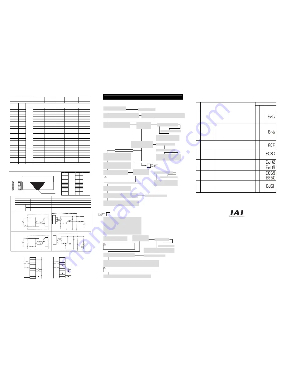
Troubleshooting
The following alarm displays are frequently generated at the start-up operation. Process it referring to the following description.
Deal with each of them referring to the following table.
Status display
Code
Status contents
Cause and Remedy
LED
Personal
Computer
TB
Panel Unit
(Option)
EMG During
emergency-stop
It is not an alarm.
•
It is generated when the emergency stop switch in the
teaching pendant or the personal computer application
software is not cancelled. In such case, cancel it.
•
It is generated when the personal computer cable is not
connected to the emergency stop box.
•
Check the emergency stop circuit.
○
enb Safety gate remains
opening
Deadman switch
OFF
It is not an alarm.
•
It is generated when the system I/O ENB signal is opened.
Check the ENB signal. (It is generated when the safety gate
is open. Close the safety gate.)
•
It is generated when the AUTO/MANU switch has been set to
“MANU” and the personal computer or the teaching pendant
is not connected. Connect the personal computer or the
teaching pendant or set the AUTO/MANU switch to “AUTO”.
•
When the actuator is to be started up, hold the deadman
switch on the teaching pendant to turn it on.
ACF AC Power
Interruption
Momentary Power
Failure
Power Voltage Drop
It is generated when the power voltage is not supplied. It will be
generated, for example, in the case that the AC100V is supplied
to the controller with AC200V specified. Check the power
supply.
CA1 Absolute Data
Backup Battery
Voltage Error
It is caused when the battery is not attached or battery voltage
drops.
In the case of the actuator for the single-axis robots or
Cartesian robots with the absolute data specifications, it is
generated when the power is connected for the first time.
Perform the absolute reset.
○
D12 Encoder
Disconnection Error
It is generated when the cable is broken or the encode cable is
not connected to the controller. Check the wiring.
○
D19 Encoder Reception
Time Out
It is generated when the encoder is broken down, the cable is
broken or the encoder cable is not connected to the controller.
Check the wiring.
○
E69
E6C
24V I/O Error
DO output current
error
It is generated when the +24V power for I/O is not supplied.
Check the power supply.
(How to start up the controller without connecting the I/O 24V
power)
Set both the I/O parameter No. 10 to “0”.
○
D5
□
Field Bus Error
It is generated when the field bus link connection is not
established.
Check the link cable connection, I/O parameter and PLC
parameter settings.
(How to start up the controller without connecting the field bus)
Set both the I/O parameter No. 10 to “0”.
○
IAI America Inc.
Head Office: 2690W 237th Street Torrance, CA 90505
TEL (310) 891-6015 FAX (310) 891-0815
Chicago Office: 1261 Hamilton Parkway Itasca, IL 60143
TEL (630) 467-9900 FAX (630) 467-9912
Atlanta Office: 1220-E Kennestone Circle,Marrietta,GA 30066
TEL (678) 354-9470 FAX (678) 354-9471
website: www.intelligentactuator.com
IAI Industrieroboter GmbH
Ober der Röth 4, D-65824 Schwalbach am Taunus, Germany
TEL 06196-88950 FAX 06196-889524
* Enter the cable length (L) in
□□□
(up to 10m)
Example) 080=8m
No.
color
Wirings
No.
color
Wirings
1A BR-1
9B GY-2
1B RD-2
10A WT-2
2A OR-1
10B BK-2
2B YW-1
11A BR-3
3A GN-1
11B RD-3
3B BL-1
12A OR-3
4A PL-1
12B YW-3
4B GY-1
13A GN-3
5A WT-1
13B BL-3
5B BK-1
14A PL-3
6A BR-1
14B GY-3
6B RD-2
15A WT-3
7A OR-2
15B BK-3
7B YW-2
16A BR-4
8A GN-1
16B RD-4
8B BL-2
17A OR-4
9A PL-2
Flat cable
(Press
welding)
17B YW-4
Flat cable
(Press
welding)
Set-up for operation is completed. Perform the system operation adjustment.
Catalogue No.: ME0209-1A
2m
Flat cable AWG28
(34 conductors)
1A
1B
17A
17B
No
connector
1A
1B
2A
13A
13B
14A
17A
17B
0V +24V
Pin No.
Load
A
→
↓
Yes
Perform the absolute reset.
Confirm the alarm description in the window
of the personal computer or teaching
pendant, and deal with it.
(Refer to the “Treatments in Error Condition”)
In the case that it has been installed vertically, repeating the
servo turning ON/OFF, might lower the unit slightly due to the
weight of the unit itself. In such case, take care so that your
hand is not caught or the work is not damaged.
* The homing operation for the absolute type is not required.
Set-up for operation is completed. Set the position and start the program.
A
PIO Pattern Settings
Set the Other Parameter No. 25.
Setting Range 1: Standard Mode
2: Item Change Mode
3: Double-Axis Independent Mode
4: Teaching Mode
16: DS-S-C1 Interchange Mode
(Refer to the Instruction Manual for the details).
Set the safety speed.
When the machine is delivered from the factory, the safety speed is
set to 250mm/s using the Parameter No. 33 common to all axes.
Change it if necessary.
Connect the motor cable.
•
To ensure safety, it is recommended that safety speed be enabled during initial movements.
•
When the unit is installed vertically and the brake release switch is set to “RLS” side, the unit might
drop due to its own weight. In such case, take care not to catch your hand or damage the handle.
No
→
→
No
→
→
↓
Yes
↓
↓
Yes
↓
No
↓
Yes
↓
No
↓
Yes
↓
↓
↓
No
→
↓
Yes
↓
Yes
↓
↓
↓
No
→
↓
Yes
↓
→
No
→
No
→
↓
Yes
No
→
↓
Yes
↓
Yes
No
→
Contact the sales shop.
Point Check Item
•
Have you perform the frame grounding and protective grounding processing.
•
Has the noise countermeasure been taken?
Power Supply and Alarm Check
Connect the personal computer or teaching
pendant, set the AUTO/MANU switch to the
[MANU] side and inject the power.
Check Item 1
Is the LED indicator
[EMG] turned off on the
front panel?
When the USB port is used, is the
dummy plug inserted to connect?
Insert the dummy plug to connect.
Check Item 1
Are the LED Indications “PWR” and
“RDY” turned ON on the front panel?
Is the LED Indication “ALM” turned OFF?
Is the actuator for Absolute?
Confirm the emergency stop switch box
connection.
Confirm that the emergency stop switch
has been cancelled.
Installation and Wiring
Install the controller and actuator and perform wiring according
to the instruction manual and the contents in this book.
Check of Packed Items
Are there all the delivered items?
PIO Pattern Settings
When the other parameter No. 25 is not set to
“0”, set it to “0”.
(When the machine is delivered from the factory,
it is set to “0”).
Parameter Setting
Set the parameters including I/O parameter with
the personal computer or teaching pendant
operation.
Servo ON
Turn ON the servo motor with the personal
computer or teaching pendant operation.
Connect the motor cable.
When the alarm is output, deal with it after
confirming the alarm description, using the
personal computer or teaching pendant
operation.
Homing Execution
Home the actuator with personal computer or
teaching pendant operation.
Check of Safety Circuit
Check that the emergency stop circuit (or motor drive power
cutoff circuit) operates normally to turn off the servo.
Check the emergency stop circuit.
Confirming the operation of the actuator
Confirm that the full stroke operation is performed without any
trouble with the jog operation.
Has the motor cable connected?
Servo ON
Turn ON the servo motor with the personal
computer or teaching pendant operation.
Has the motor cable
connected?
Confirm the alarm description in the window of the
personal computer or teaching pendant, and deal with it.
(Refer to the “Treatments in Error Condition”)
Check the emergency stop circuit.
Check of Safety Circuit
Check that the emergency stop circuit (or motor drive-power
cutoff circuit) operates normally to turn off the servo.
Target Position Setting
Set a target position in the “Position” field for each position in the position table.
When carrying out direct teaching, perform home return operation first.
When the unit is equipped with the brake, move it after setting the brake release switch to “RLS” side.
Confirming the operation of the actuator
Confirm that the full stroke operation is performed without any trouble with the jog operation.
←
In the case of Program Mode:
In the case of Positioner Mode:
Check Item
Are the LED Indications
“SV1” and “SV2” for the
turned ON axes turned ON?
In the case that it has been installed vertically, repeating the
servo turning ON/OFF, might lower the unit slightly due to the
weight of the unit itself. In such case, take care so that your
hand is not caught or the work is not damaged.
Check Item
Are the LED Indications
“SV1” and “SV2” for the
turned ON axes turned ON?
1A
1B
2A
13A
13B
14A
17A
17B
0V
+24V
Pin No.
Load