


EtherNet/IP
●
Specification
Item Specification
Communication protocol
IEC61158 (IEEE802.3)
Communication speed
10BASE-T/100BASE-T (Autonegotiation setting is recommended)
Communication cable length Depends on EtherNet/IP Specification
(Distance between hub and each node : 100m or less)
Number of connection
Depends on the master unit
Applicable node address
0.0.0.0 to 255.255.255.255
Communication cable
Category 5 or more
(Double shielded cable braided with aluminum foil recommended)
Connector RJ45
Connector
×
1pc
●
Interface Section
●
Status LED Displays of EtherNet/IP Type
Name Indication
Color
Description
OFF
Power is OFF or IP addresses are not set
GN (Illuminating) Connection is established and the communication under normal condition.
GN (Flashing)
Online but network connection is not yet established. Communication Stop
(Network is normal). Check the conditions of master unit.
RD (Illuminating)
Communication Error.
Communication cannot be
established due to the error detection
such as IP address duplication.
NS
RD (Flashing)
Communication Error.
(Communication Time-out Detection)
Check the conditions of IP
address settings, communication
line, the power of hub units, noise
prevention, etc.
OFF Power
OFF
GN (Illuminating)
The machine is in the normal operation.
The machine is under the control of the scanner (master)
GN (Flashing)
The connection with the scanner (master) is not established.
Check the construction information settings.
Check if the scanner (master) is in the idle condition.
RD (Illuminating)
Hardware Error.
The replacement of the board is required. Please contact us.
MS
RD (Flashing)
There is an error occurred but is not critical such like a user setting error or
configuration error. It can be recovered with a rebuild of the settings.
●
EherNet/IP Connector
Pin No.
Signal Name
Abbreviated Code
1
Data sending
+
TD
+
2
Data sending
−
TD
−
3
Data receiving
+
RD
+
4 Not
used
5 Not
used
6
Data receiving
−
RD
−
7 Not
used
8 Not
used
Connector Hood
Security grounding
FG
●
Operation Mode Setting and Address Allocation
The operation mode is set using the parameters.
Set the mode change switch on the controller front panel to “MANU” side and set the parameter No. 84
“FMOD: Field Bus Operation Mode” using the teaching tool such as PC software for RC.
[Refer to the Instruction Manual for the details]
●
Communication Speed Setting
The Communication speed can be set with the parameter. A special setting is not necessary since it is set
to automatic negotiation when the product is delivered. However, when a fixed speed is required, change
the setting to the desired speed in the parameter No. 86 “FBRS: Fieldbus Communication Speed” using
the teaching tool such as PC software for RC.
[Refer to the Instruction Manual for the details]
●
IP Address Setting
IP Address can be set with the parameter.
Set the parameter No. 140 “IPAD: IP Address” using the teaching tool such as PC software for RC.
Settable Range : 0.0.0.0 to 255.255.255.255 (It is set to “192.168.0.1” when the machine is delivered
from the factory.)
●
Settings for Subnet Mask
Subnet Mask can be set with the parameter.
Set the parameter No. 141 “SNMK: Subnet Mask” using the teaching tool such as PC software for RC.
Settable Range : 0.0.0.0 to 255.255.255.255 (It is set to “255.255.255.0” when the machine is delivered
from the factory.)
●
Settings for Default Gateway
Default Gateway can be set with the parameter.
Set the parameter No. 142 “DFGW: Default Gateway” using the teaching tool such as PC software for RC.
Settable Range : 0.0.0.0 to 255.255.255.255 (It is set to “0.0.0.0” when the machine is delivered from the factory.)
PROFINET IO
●
Specification
Item Specification
Communication protocol
IEC61158 (IEEE802.3), IEC61748
Communication speed
100Mbps
Communication cable length Distance between each segment: 100m Max.
Number of connection
Depends on the master unit
Applicable node address
0.0.0.0 to 255.255.255.255
Communication cable
Category 5 or more
(Double shielded cable braided with aluminum foil recommended)
Connector RJ45
Connector
×
1pc
GSDML file version
Ver 2.3
●
Interface Section
SCON-CA SCON-CAL/CGAL
●
Status LED Displays of PROFINET IO Type
Name Indication
Color
Description
OFF
Power is OFF, or there is no connectable controller.
GN
(Illuminating)
Connection has been established and proper communication is in
progress. (in RUN condition) Check the condition of the master unit.
NS
GN (Flashing)
Connection is established but communication is paused (in STOP
condition: network in normal condition). Check the condition of the master
unit.
OFF
The power is turned OFF.
GN
(Illuminating)
Operation is normal.
GN (Flashing)
Communication under diagnosis
OR
(Illuminating)
A hardware error is present. (in EXCEPTION condition)
The board must be replaced. Please contact IAI.
OR (Flashing 1) There is an error in communication setting.
OR (Flashing 2) There is an error in IP address setting.
OR (Flashing 3) A wrong station name has been applied.
MS
OR (Flashing 4)
A hardware error is present. (Critical internal error)
The board must be replaced. Please contact IAI.
OFF
No link or activity
GN
(Illuminating)
Link established
Link/Activity
(There is
limitation in
applicable
models)
GN (Flashing)
In activity (communication)
Orange (Flashing 1): Repeating of off for 0.75s and on for 0.25s
Orange (Flashing 2): Repeating two times of pattern of off for 0.75s and on for 0.5s
Orange (Flashing 3): Repeating three times of pattern of off for 0.75s and on for 0.5s
Orange (Flashing 4): Repeating four times of pattern of off for 0.75s and on for 0.5s
●
EherNet/IP Connector
Pin No.
Signal Name
Abbreviated Code
1
Data sending
+
TD
+
2
Data sending
−
TD
−
3
Data receiving
+
RD
+
4 Not
used
5 Not
used
6
Data receiving
−
RD
−
7 Not
used
8 Not
used
Connector Hood
Security grounding
FG
●
Operation Mode Setting and Address Allocation
The operation mode is set using the parameters.
Set the mode change switch on the controller front panel to “MANU” side and set the parameter No. 84
“FMOD: Field Bus Operation Mode” using the teaching tool such as PC software for RC.
[Refer to the Instruction Manual for the details]
●
Communication Speed Setting
It is not necessary to establish setting. It is fixed at 100Mbps.
●
Node address setting
It is not necessary to establish setting on the IAI controller side as it should be established on the master side.
[Refer to the instruction manual of the host unit that the master unit is mounted in.]
(Note) After parameter setting, reset the controller mode change witch to “AUTO” side, and then cycle the
controller power.
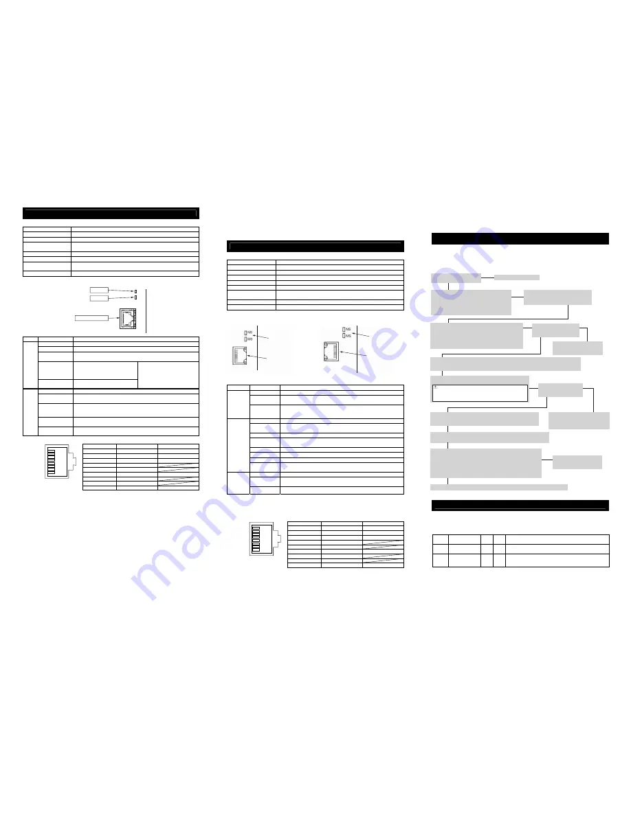
Starting Procedures
When using this product for the first time, make sure to avoid mistakes and incorrect wiring by referring to
the procedure below
In this section, explains how to start up SCON complied with EtherCAT®, EtherNet/IP and PROFINET IO
(described as the “controller” in the following diagram). Refer to each Instruction Manual for the installation
and wiring of the equipment, controller, actuator and all other devices that are connected to the network.
Trouble Shooting
In the case an error is occurred, check the operation status on the LED display on the front panel [Refer to
Each Fieldbus Section], and also, check the status monitor by connecting a teaching tool such as PC
software for RC.
Either of the following alarms will be shown for Fieldbus. Please refer to the Instruction Manual of the
controller for other alarms to perform an appropriate treatment.
Code
Error Name
ID
(*1)
RES
(*2)
Cause / Treatment
0F2
Fieldbus
Module Error
05 ×
Cause
: An error is detected on Fieldbus module
Treatment : Check on the parameter
0F3
Fieldbus Module
Not Detected
04 ×
Cause
: Module cannot be detected
Treatment : Turn the power off and reboot. Please contact us
if the problem is not solved with this action.
(*1) ID
→
Simple alarm code
(*2) RES
→
Alarm reset available/unavailable
○
: Alarm reset available / ×: Alarm reset unavailable
1
8
RJ45 8-pin
Modular Connector
(Controller Side)
Check of Packed Items
Are there all the delivered items?
Installation and Wiring
Follow Instruction Manual and this manual to
install the controller and connect to the network.
Also, perform the wirings of the motor and encoder
cables for the power supply unit and the actuators
following the Instruction Manual of each controller.
To turn ON the controller
1) Set the mode switch on the front panel to MANU side.
2) Set the brake release switch on the front panel to NOM side.
3) Connect a teaching tool such as the PC software.
4) Turn the power ON and start up the teaching tool with
“Teaching Mode Safety Speed Valid” setting.
Controller Initial Settings
Refer to each fieldbus section to perform the necessary parameter settings of the modes, addresses, etc.
• Set Parameter No. 35 Safety Speed if necessary. (Initial Value: 100mm/s)
Servo ON
Turn the servo ON by operating the controller.
Contact us or our distributor.
Point Check Item
• Is frame ground (FG) connected?
• Has the noise countermeasure been taken?
Important Check Item
Is the status display LED (ALM)
on the front panel turned off?
Check the detail of the alarm on
the teaching tool and have an
appropriate treatment.
Yes↓
No↓
→
→
No→
↓Yes
←Yes
↓
↓
Note (In the case that the actuator is in vertical mount)
When the machine is turned ON/OFF repeatedly at the same
position, it might be lowered slightly due to its own weight.
Take care not to catch your hand or damage the work.
Check of Safety Circuit
Check that the emergency stop circuit (or motor drive-power cutoff
circuit) operates normally to turn OFF the servo.
Important Check Item
Is the status display LED (SV)
turned on in green?
If an alarm is generated (status display
LED (ALM) is on in red), check the detail
of the alarm on the teaching tool and
have an appropriate treatment.
Settings on Host System
Refer to PLC Instruction Manual to perform the communication settings and so on.
Refer to the Instruction Manual
for each unit, controller and PLC
to check each setting.
No↓
Yes↓
↓Yes
↓
↓
→
No→
Communication is now established. Perform an operation check and adjustment for the system.
Confirming Communication Establishment
• Confirm the communication is established on the status LED (RUN)
on the front panel. [Refer to the troubleshooting]
• Is the LED status in normal condition? Is PLC (master unit) side also
in normal condition?
(Note) Refer to PLC and master unit Instruction Manuals for how to check
the master unit side.
1
8
RJ45 8-pin
Modular Connector
(Controller Side)
Status LED
NS LED
MS LED
EtherNet/IP Port
(Note) After parameter setting, reset the controller mode change witch to “AUTO” side, and then cycle
the controller power.
EtherNet/IP
Communication Port
Monitoring LED
EtherNet/IP
Communication Port
Monitoring LED


