


● EtherCAT® Connector
Pin No.
Signal Name
Abbreviated Code
1
Data s
TD
+
2
Data sending -
TD
−
3
Data rec
RD
+
4
Not used
5
Not used
6
Data receiving -
RD
−
7
Not used
8
Not used
Connector Hood
Security grounding
FG
● Operation Mode Setting and Address Allocation
The operation mode is set using the parameters.
Set the mode change switch on the controller front panel to “MANU” side and set the parameter No.84
“FMOD: Fieldbbus Operation Mode” using the teaching tool such as PC software for RC.
[Refer to the Instruction Manual for the details]
● Node address setting
Node address can be set with the parameter.
Set Parameter No.85 “NADR: Fieldbus Node Address” with a teaching tool such as PC software for RC.
Settable Range: 0 to 127 (It is set to 17 which is the I/O slave top address of EtherCAT® at the delivery.)
● Communication Speed Setting
The setting for the communication speed is not required because it automatically follows the master’s
communication speed.
(Note) After parameter setting, reset the controller mode change witch to “AUTO” side, and then cycle the controller power.
EtherNet/IP
● Specification
Item
Specification
Communication Protocol
IEC61158 (IEEE802.3)
Communication Speed
10BASE-T/100BASE-T (Autonegotiation setting is recommended)
Communication Cable Length
Depends on EtherNet/IP Type
(Distance between hub and each node: 100m max.)
Number of Connection
Depends on the master unit
Applicable Node Address
0.0.0.0 to 255.255.255.255
Communication Cable
Category 5 or more
(Double shielded cable braided with aluminum foil recommended)
Connector
RJ45 Connector
×
1pc
● Interface Section
(Note) Refer to the troubleshooting or the Instruction Manual for the details of LED displays.
● EtherNet/IP Connector
Pin No.
Signal Name
Abbreviated Code
1
Data s
TD
+
2
Data sending -
TD
−
3
Data rec
RD
+
4
Not used
5
Not used
6
Data receiving -
RD
−
7
Not used
8
Not used
Connector Hood
Security grounding
FG
● Operation Mode Setting and Address Allocation
The operation mode is set using the parameters.
Set the mode change switch on the controller front panel to “MANU” side and set the parameter No.84
“FMOD: Fieldbus Operation Mode” using the teaching tool such as PC software for RC.
[Refer to the Instruction Manual for the details]
● Communication Speed Setting
The Communication speed can be set with the parameter. A special setting is not necessary since it is set
to automatic negotiation when the product is delivered. However, when a fixed speed is required, change
the setting to the desired speed in Parameter No.86 “FBRS: Fieldbus Communication Speed” of the
teaching tool in the PC software for RC.
[Refer to the Instruction Manual for the details]
● IP Address Setting
IP Address can be set with the parameter.
Set Parameter No.140 “IPAD: IP Address” with a teaching tool such as PC software for RC.
Settable Range: 0.0.0.0 to 255.255.255.255 (It is set to “192.168.0.1” when the machine is delivered from
the factory.)
● Settings for Subnet Mask
Subnet Mask can be set with the parameter.
Set Parameter No.141 “SNMK: Subnet Mask” with a teaching tool such as PC software for RC.
Settable Range: 0.0.0.0 to 255.255.255.255 (It is set to “255.255.255.0” when the machine is delivered
from the factory.)
● Settings for Default Gateway
Default Gateway can be set with the parameter.
Set Parameter No.142 “DFGW: Default Gateway” with a teaching tool such as PC software for RC.
Settable Range: 0.0.0.0 to 255.255.255.255 (It is set to “0.0.0.0” when the machine is delivered from the
factory.)
(Note) After parameter setting, reset the controller mode change witch to “AUTO” side, and then cycle the controller power.
PROFINET-IO
● Specification
Item
Specification
Communication protocol
IEC61158 (IEEE802.3), IEC61748
Communication Speed
100Mbps
Communication cable length
Depends on PROFINET-IO Specification
(Distance between each segment: 100m Max.)
Number of Connection
Depends on the master unit
Applicable node address
0.0.0.0 to 255.255.255.255
Communication cable
Category 5 or more
(Double shielded cable braided with aluminum foil recommended)
Connector
RJ45 Connector
×
1pc
● Interface Section
(Note) Refer to the troubleshooting or the Instruction Manual for the details of LED displays.
● EherNet/IP Connector
Pin No.
Signal Name
Abbreviated Code
1
Data sending
+
TD
+
2
Data sending
−
TD
−
3
Data receiving
+
RD
+
4
Not used
5
Not used
6
Data receiving
−
RD
−
7
Not used
8
Not used
Connector Hood
Security grounding
FG
● Operation Mode Setting and Address Allocation
The operation mode is set using the parameters.
Set the mode change switch on the controller front panel to “MANU” side and set the parameter No. 84
“FMOD: Field Bus Operation Mode” using the teaching tool such as PC software for RC.
[Refer to the Instruction Manual for the details]
● Communication Speed Setting
It is not necessary to establish setting. It is fixed at 100Mbps.
● Node address setting
It is not necessary to establish setting on the IAI controller side as it should be established on the master
side.
(Note) After parameter setting, reset the controller mode change witch to “AUTO” side, and then cycle the controller power.
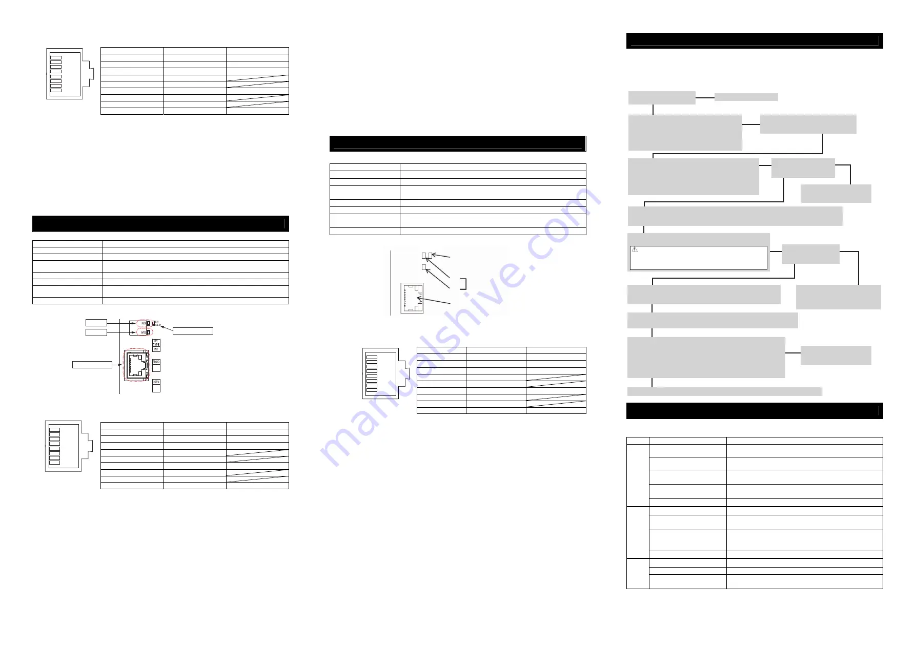
Starting Procedure
When using this product for the first time, make sure to avoid mistakes and incorrect wiring by referring to
the procedure below.
This section explains how to start up an EtherCAT®, EtherNet/IP and PROFINET-IO complaint PCON,
ACON and DCON (described as the “controller” in the following diagram). For the settings and wiring of each
of the individual devices, controllers, and actuators connected to the network, refer to the individual device’s
Instruction Manual.
Trouble Shooting
If an error has occurred, it is possible to check the operation condition on the status LEDs on the front panel.
● Status LED Displays of EtherCAT® Type
{
: Illuminating,
×
: OFF,
☆
: Flashing
Name
Indication Color
Description
×
Initial condition (EtherCAT® communication in “INIT” condition) or the
power is OFF
{
(GN)
In normal operation (EtherCAT® communication in “OPERATION”
condition)
☆
(GN)
(ON: 200ms/OFF: 200ms)
(EtherCAT® communication in “PRE-OPERATION” condition)
☆
(GN)
(ON: 200ms/OFF: 1000ms)
(EtherCAT® communication in “SAFE-OPERATION” condition)
RUN
{
(OR)
Communication component (module) error
×
No abnormality or the power is OFF
☆
(OR)
(ON: 200ms/OFF: 200ms)
Construction information (settings) error
(Information received from the master cannot be set)
☆
(OR)
(ON: 200ms
×
2 times/
OFF: 1000ms)
Communication section circuit error
(Watchdog timer timeout)
ERR
{
(OR)
Communication component (module) error
×
Link status not detected or the power is OFF
{
(GN)
Linked (No network congestion)
Link/
Activity
☆
(GN)
(ON: 50ms/OFF: 50ms)
Linked (Network in congestion)
1
8
RJ45 8-pin
Modular Connector
(Controller side)
1
8
RJ45 8-pin
Modular Connector
(Controller side)
NS LED
MS LED
EtherNet/IP Port
Status LED
Status Diplay LED
Check of Packed Items
Has everything been received?
Installation and Wiring
Follow Instruction Manual and this manual to install the
controller and connect to the network.
Also, perform the wirings of the motor and encoder
cables for the power supply unit and the actuators
following the Instruction Manual of each controller.
To turn ON the controller
1) Set the mode switch on the front panel to MANU side.
2) Set the brake release switch on the front panel to NOM side.
3) Connect a teaching tool such as the PC software.
4) Turn the power ON and start up the teaching tool with
“Teaching Mode Safety Speed Valid” setting.
Controller Initial Settings
Refer to each fieldbus section to perform the necessary parameter settings of the modes, addresses, etc.
• Set Parameter No.35 Safety Speed if necessary. [Initial Value: 100mm/s]
Servo ON
Turn the servo ON by operating the teaching tool.
Contact us or our distributor.
Point Check Item
• Is frame ground (FG) connected?
• Has the noise countermeasure been taken?
Important Check Item
Is the status display LED on
the front panel turned OFF?
Check the detail of the alarm on
the teaching tool and remedy
any errors.
Yes↓
No↓
→
→
No→
↓Yes
←Yes
↓
↓
Note (In the case that the actuator is in vertical mount)
When the machine is turned ON/OFF repeatedly at the same
position, the actuator position may lower slightly due to its own
weight. Take care not to catch your hand or damage the work.
Check of Safety Circuit
Check that the emergency stop circuit (or motor drive-power cutoff circuit)
operates normally to turn OFF the servo.
Important Check Item
Is the status display LED
turned ON in green?
If an alarm is generated (status display
LED is ON in red), check the detail of
the alarm on the teaching tool and
remedy any errors.
Settings on Host System
Refer to PLC Instruction Manual to perform the communication settings and so on.
Refer to the Instruction Manual
for each unit, controller and PLC
to check each setting.
No↓
Yes↓
↓Yes
↓
↓
→
No→
Communication is now established. Perform an operation check and adjustment for the system.
Confirming Communication Establishment
• Confirm the communication is established on the status LED on the front
panel. [Refer to the troubleshooting]
• Is the LED status in normal condition? Is PLC (master unit) side also
in normal condition?
(Note) Refer to PLC and master unit Instruction Manuals for how to check
the master unit side.
1
8
RJ45 8-pin
Modular Connector
(Controller Side)
PROFINET-IO Port
NS
MS
Monitoring LED
SV/ALM Status Display LED


