


PCON-CA/CFA/CB/CFB,
ACON-CA/CB/CGB, DCON-CA/CB/CGB
First Step Guide Sixth Edition
Thank you for purchasing our product.
Make sure to read the Safety Guide and detailed Instruction Manual (DVD) included with the product in addition to this First
Step Guide to ensure correct use. This Instruction Manual is original.
•
Using or copying all or part of this Instruction Manual without permission is prohibited.
•
The company names, names of products and trademarks of each company shown in the sentences are registered
trademarks.
•
EtherCAT® is a registered mark of Beckoff Automation GmbH.
•
EtherNet/IP is a trademark used under the license of ODVA.
Product Check
The standard configuration of this product is comprised of the following parts.
If you find any fault with the product you have received, or any missing parts, contact us or our distributor.
1. Parts
No.
Part Name
Model
Reference
1
Controller Main Body
Refer to “How to read the model plate”, “How to read
the model of the controller”
Accessories
2
Power Connector
FMC1.5/8-ST-3.5 (Supplier : PHOENIX CONTACT)
Recommended cable size
AWG16 to 20
(1.25 to 0.5mm
2
)
3
Absolute Battery (Option)
AB-7 or SEP-ABU*
If applicable for Simple Absolute
Type
4
Serial Absolute Battery (Option) AB-5
If applicable for Serial Absolute
Type (for ACON only)
5
First Step Guide
6
Instruction Manual (DVD)
7
Safety Guide
2. Teaching Tool (to be purchased separately)
A teaching tool, such as PC Software, is necessary when performing programming and commissioning, such
as editing position data or parameters.
Please utilise any of the following teaching tools.
No.
Part Name
Model
1
PC Software
(with RS232C converter adapter
+
external equipment communication cable)
RCM-101-MW
2
PC Software
(with USB converter adapter
+
USB cable
+
external equipment communication cable)
RCM-101-USB
3
Touch Panel Teaching
TB-01
4
Touch Panel Teaching (with Deadman Switch Attached on the Left side)
TB-01D
5
Touch Panel Teaching (with Deadman Switch Attached on the Right side)
TB-01DR
6
Touch Panel Teaching
CON-PTA
7
Touch Panel Teaching (with Deadman Switch)
CON-PDA
8
Touch Panel Teaching (with Deadman Switch
+
TP Adapter (RCB-LB-TG))
CON-PGAS
3. Instruction Manuals related to this product, which are contained in the Instruction Manual (DVD).
No.
Name
Manual No.
1
PCON-CA/CFA Controller Instruction Manual
ME0289
2
PCON-CB/CFB Controller Instruction Manual
ME0342
3
ACON-CA, DCON-CA Controller Instruction Manual
ME0326
4
ACON-CB Series Controller, DCON-CB Series Controller, Instruction Manual
ME0343
5
PC Software
RCM-101-MW/RCM-101-USB Instruction Manual
ME0155
6
Touch Panel Teaching
CON-PTA/PDA/PGA Instruction Manual
ME0295
7
Instruction Manual for the Serial Communication [for Modbus]
ME0162
8
CC-Link Instruction Manual
ME0254
9
DeviceNet Instruction Manual
ME0256
10 PROFIBUS-DP Instruction Manual
ME0258
11 CompoNet Instruction Manual
ME0220
12 MECHATROLINK-
Ⅰ
/
Ⅱ
Instruction Manual
ME0221
13 EtherCAT Instruction Manual
ME0273
14 EtherNet/IP Instruction Manual
ME0278
15 PROFINET-IO Instruction Manual
ME0333
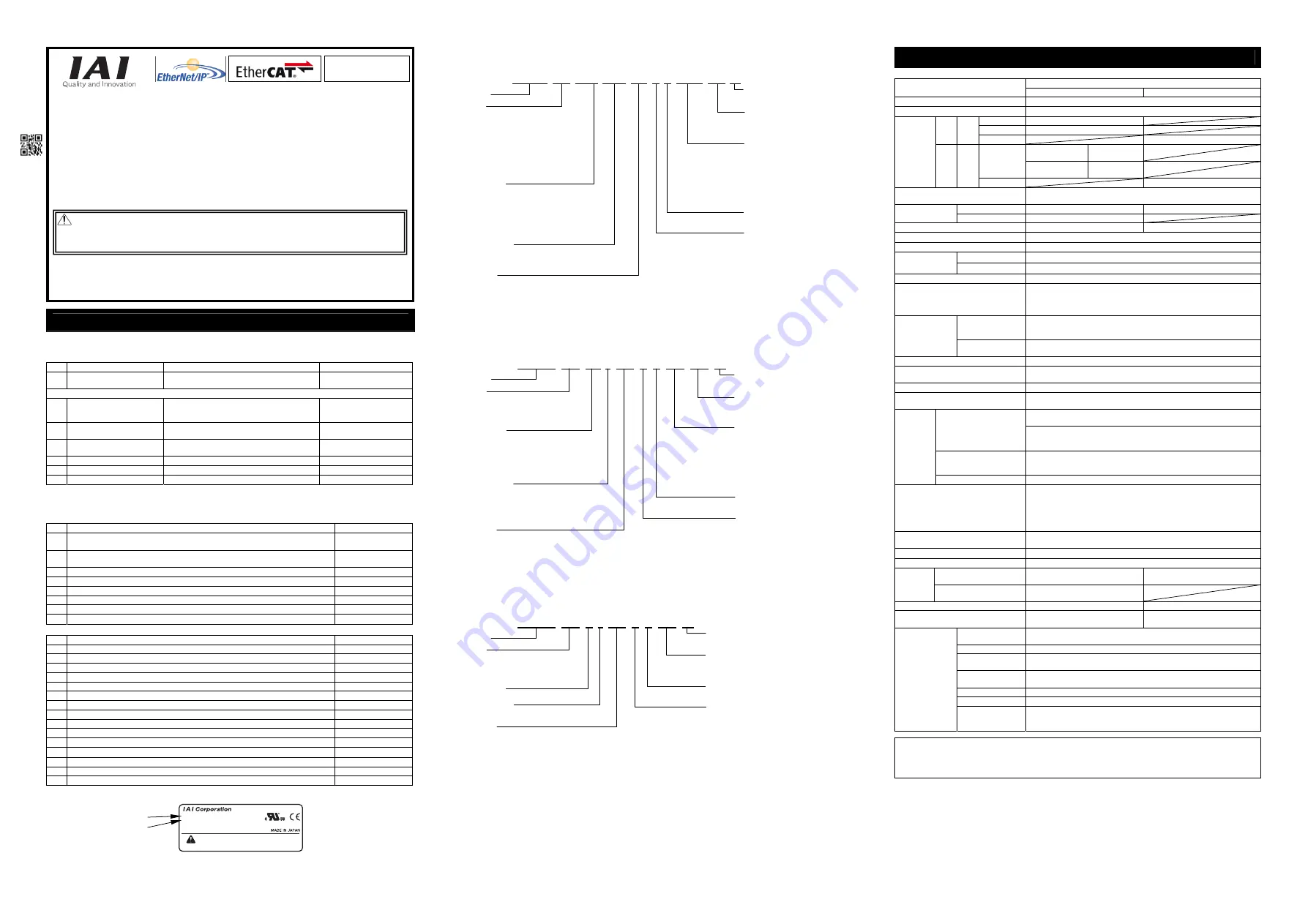
4. How to read the model plate
5. How to read the model of the controller
z
PCON
P C O N - C A - 5 6 P W A I - E P - 2 - 0 - A B U - D N - * *
z
ACON
A C O N - C A - 3 0 I - E C - 2 - 0 - A B - D N - * *
z
DCON
D C O N - C A - 3 I - E P - 2 - 0 - D N - * *
Basic Specifications
PCON List of Specifications
Description
Item
PCON-CA/CB/CGB
PCON-CFA/CFB/CGFB
Number of controlled axes
1-axis
Power-supply Voltage
24V DC
±
10%
20P, 28P, 28SP MAX. 1A
42P, 56P
MAX. 2A
RCP2
RCP3
Motor
Type
86P
Rated 4.2A / MAX. 6A
High-thrust function
is disabled
MAX.2.0A
28P, 35P, 42P,
56P
High-thrust function
is enabled
Rated 3.5A /
MAX. 4.2A
Load
Capacity
(including
control side
current
consumption)
(Note1)
RCP4
RCP5
RCP6
Motor
Type
60P, 86P
Rated 4.2A / MAX. 6A
Power Supply for Electromagnetic Brake
(for actuator equipped with brake)
24V DC
±
10% 0.15A (MAX.)
RCP2, RCP3
5W
26.4W
Heat Generation
RCP4 to RCP6
3W
Rush Current
(Note2)
8.3A
10A
Transient Power Cutoff Durability
MAX. 500
μ
s
Motor Control System
Weak field-magnet vector control
RCP2 to RCP5
Incremental Encoder, Battery-less Encoder Resolution 800pulse/rev
Corresponding
Encoder
RCP6
Battery-less Encoder Resolution 8192pulse/rev
Actuator Cable Length
MAX. 20m
Serial Communication Interface
(SIO Port)
RS485 : 1 CH (based on Modbus Protocol RTU/ASCII)
Speed : 9.6 to 230.4Kbps
Control available with serial communication in the modes other than the pulse
train
PIO Type
Signal I/O dedicated for 24V DC (selected from NPN/PNP) … Input 16 points
max., output 16 points max.
Cable length MAX. 10m
External Interface
Fieldbus Type
DeviceNet, CC-Link, PROFIBUS-DP, CompoNet, MECHATROLINK,
EtherCAT, EtherNet/IP, PROFINET-IO
Data Setting and Input
PC Software, Touch Panel Teaching, Teaching Pendant
Data Retention Memory
Saves position data and parameters to non-volatile memory
(There is no limitation to the number of times data may be written.)
Operation Mode
Positioner Mode/Pulse Train Control Mode (selected by parameter setting)
Number of Positions in Positioner Mode
Standard 64 points, MAX. 512 points (PIO Type)
(Note) Number of positions differs depending on the selection in PIO pattern.
Differential System (Line Driver System) : MAX. 200kpps
Cable length MAX. 10m
Input Pulse Frequency
Open Collector System : Not applicable.
* If the host applies the open collector output, prepare AK-04 (option) separately
to convert to the differential type.
Command Pulse Multiplying
Factor
(Electrical Gear : A/B)
1/50
<
A/B
<
50/1
Setting Range of A and B (set to parameter) : 1 to 4096
Pulse Train
Interface
Feedback Pulse Output
None
LED Display
(mounted on Front Panel)
SV (GN)/ALM (RD) : Servo ON/Alarm generated
STS0 to 3
: Status display
RDY (GN)/ALM (RD) : Absolute function in normal / absolute function error (for
the simple absolute type)
1, 0 (GN) (RD)
: Absolute function status display (for the simple absolute
type)
Electromagnetic Brake Compulsory
Release Switch (mounted on Front Panel)
Switching NOM (standard)/BK RLS (compulsory release)
Insulation Resistance
500V DC 10M
Ω
or more
Protection Function against Electric Shock Class I basic insulation
Incremental Type
Screw fixed type : 250g or less
DIN rail fixed type : 285g or less
Screw fixed type : 270g or less
DIN rail fixed type : 305g or less
Weight
(Note3)
Simple Absolute Type
(including 190g for battery)
Screw fixed type : 450g or less
DIN rail fixed type : 485g or less
Cooling Method
Natural air-cooling
Forced air-cooling
External dimensions
Screw fixed type : 35W×178.5H×69.1D
DIN rail fixed type : 35W×185H×77.6D
Screw fixed type : 35W×190H×69.1D
DIN rail fixed type : 35W×196.3H×77.6D
Surrounding Air
Temperature
0 to 40
°
C
Surrounding Humidity 85%RH or less (non-condensing)
Surrounding
Environment
[Refer to Installation Environment]
Surrounding Storage
Temperature
-20 to 70
°
C (Excluding battery)
Usage Altitude
1000m or less
Protection Class
IP20
Environment
Vibration Durability
Frequency 10 to 57Hz / Swing width : 0.075mm
Frequency 57 to 150Hz / Acceleration 9.8m/s
2
XYZ directions Sweep time : 10 minutes Number of sweep : 10 times
Note1 Add an additional 0.3A inrush for Fieldbus Types.
Note2 In-rush current will flow for approximately 5msec after the power is turned on (at 40
°
C).
Note that the value of in-rush current differs depending on the impedance of the power supply line.
Note3 Add an additional 30g for Fieldbus Type of CA/CB/CGB Type. Add an additional 10g for Fieldbus Type of
CFA/CFB/CGFB Type .
Warning : Operation of this equipment requires detailed installation and operation instructions which are
provided on the DVD Manual included in the box this device was packaged in. It should be retained
with this device at all times.
A hardcopy of the Manual can be requested by contacting your nearest IAI Sales Office listed at
the back cover of the Instruction Manual or on the First Step Guide.
Serial number
Model
Model
SER NO.
Input
Output
Actuator
*
*
CAUTION: Connect the wiring correctly and
properly, use IAI specified cables
or min 60°C Cu wire.
IP20
*********
*********
DC24V A
0-24Vac,3ph,0-333Hz, A
*****
<Series>
<Type>
CA/CB
:
Standard Type
CFA/CFB :
High-Thrust Actuator
Connection Type
CGB
:
Sagety Categories Complied Type
CGFB
:
High-Thrust Actuator
Connection Sagety Categories
Complied Type
<Detail of Connected Axis>
[Motor Type]
20P : 20□ pulse motor, 20SP : 20□ pulse motor,
28P : 28□ pulse motor, 28SP : 28□ pulse motor,
35P : 35□ pulse motor
42P : 42□ pulse motor, 42SP : 42□ pulse motor
56P : 56□ pulse motor, 56SP : 56□ pulse motor
60P : 60□ pulse motor, 86P : 86□ pulse motor
[Encoder Type]
WAI : Incremental / Battery-less Absolute Shared
SA : Simple Absolute
<I/O Type>
NP : NPN Type (Sync. Type) (Standard),
PN : PNP Type (Source Type),
PLN : Pulse Train Control NPN Type (Sync. Type),
PLP : Pulse Train Control PNP Type (Source Type),
DV : DeviceNet Connection Type,
CC : CC-Link Connection Type,
PR : PROFIBUS-DP Connection Type,
CN : CompoNet Connection Type,
ML : MECHATROLINK-
Ⅰ
/
Ⅱ
Connection Type, EC : EtherCAT Connection Type,
EP : EtherNet/IP Connection Type,
PRT : PROFINET-IO Connection Type
<Identification for IAI use only>
* There is no identification in some cases.
<Type of Installation>
(Not Specified) : Screw Attachment Type
DN
: DIN Rail Mounting Type
<Applicable to Simplified Absolute Unit>
AB
: Simple Absolute Type
(With the Absolute Battery)
ABU : Simple Absolute Type
(With the Absolute Battery Unit
(SEP-ABU))
ABUN : Simple Absolute Type
(With no Absolute Battery)
<Power-supply Voltage>
0 : 24V DC
<I/O Cable Length>
0 : Equipped with no cable
2 : 2m (Standard)
3 : 3m
5 : 5m
<Series>
<Type>
CA/CB : Standard Type
CGB
: Safety Categories Complied Type
<Detail of Connected Axis>
[Motor Type]
2
: 2W AC servo motor
5
: 5W AC servo motor
10 : 10W AC servo motor
20S : 20W AC servo motor
20 : 20W AC servo motor
30 : 30W AC servo motor
[Encoder Type]
WAI : Incremental/Battery-less Absolute Shared
(CB dedicated)
I
: Incremental
A
: Absolute
<I/O Type>
NP : NPN Type (Sync. Type) (Standard),
PN : PNP Type (Source Type),
PLN : Pulse Train Control NPN Type (Sync. Type),
PLP : Pulse Train Control PNP Type (Source Type),
DV : DeviceNet Connection Type,
CC : CC-Link Connection Type,
PR : PROFIBUS-DP Connection Type,
CN : CompoNet Connection Type,
ML : MECHATROLINK-
Ⅰ
/
Ⅱ
Connection Type, EC : EtherCAT Connection Type,
EP : EtherNet/IP Connection Type,
PRT : PROFINET-IO Connection Type
<Identification for IAI use only>
* There is no identification in some cases.
<Type of Installation>
(Not Specified) : Screw Attachment Type
DN
: DIN Rail Mounting Type
<Applicable to Simplified Absolute Unit>
AB
: Simple Absolute Type
(With the Absolute Battery)
ABU : Simple Absolute Type
(With the Absolute Battery Unit
(SEP-ABU))
ABUN : Simple Absolute Type
(With no Absolute Battery)
<Power-supply Voltage>
0 : 24V DC
<I/O Cable Length>
0 : Equipped with no cable
2 : 2m (Standard)
3 : 3m
5 : 5m
<Series>
<Type>
CA/CB : Standard Type
CGB
: Safety Categories Complied Type
<Detail of Connected Axis>
[Motor Type]
3
:
2.5W DC Brushless motor
[Encoder Type]
I
: Incremental
<I/O Type>
NP : NPN Type (Sync. Type) (Standard),
PN : PNP Type (Source Type),
PLN : Pulse Train Control NPN Type (Sync. Type),
PLP : Pulse Train Control PNP Type (Source Type),
DV : DeviceNet Connection Type,
CC : CC-Link Connection Type,
PR : PROFIBUS-DP Connection Type,
CN : CompoNet Connection Type,
ML : MECHATROLINK-
Ⅰ
/
Ⅱ
Connection Type, EC : EtherCAT Connection Type,
EP : EtherNet/IP Connection Type,
PRT : PROFINET-IO Connection Type
<Identification for IAI use only>
* There is no identification in some cases.
<Type of Installation>
(Not Specified) : Screw Attachment Type
DN
: DIN Rail Mounting Type
<Power-supply Voltage>
0 : 24V DC
<I/O Cable Length>
0 : Equipped with no cable
2 : 2m (Standard)
3 : 3m
5 : 5m
PROFINET-IO


