


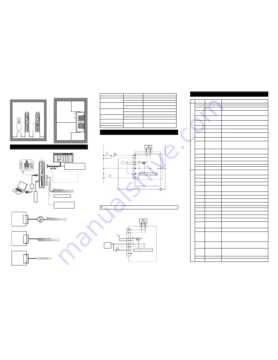
PC Software
(to be purchased
separately)
Actuator
PLC (Please prepare separately)
Power Source I/O Control
(24V DC
…Please prepare separately)
Emergency Stop Circuit
Control/Driving Power Supply
(24V DC
…Please prepare separately)
AK -04
Way to lay out wirings differs
depending on the specifications of
the host when pulse train control
mode (for PLN and PLP types only).
[Refer to Pulse Train Mode
Operation described later.]
Controller Status
Display LED
Teaching Pendant
Touch Panel Teaching
(to be purchased separately)
4. Heat Radiation and Installation
Design and Build the system considering the size of the controller box, location of the controller and
cooling factors to keep the ambient temperature around the controller below 40
°
C
Connection Diagram
●
Connection to RCP2 (High-Thrust), RCA and RCL Series
PCON
ACON
Motor/
Encoder Connector
Connection
Cable
(Note1)
●
Connection to RCP3, RCP4, RCP5 and RCA2 Series
Connection
Cable
(Note1)
PCON
ACON
Motor/
Encoder Connector
●
Connection to RCD Series
Connection
Cable
(Note1)
DCON
Motor/
Encoder Connector
Note 1 Applicable Connection Cable Model Codes
□□□
: Cable Length Example) 030 = 3m
Model Name
Cable
Reference
RCP2 CB-PSEP-MPA
□□□
Robot cable from 0.5 to 20m
CB-APSEP-MPA
□□□
Robot cable from 0.5 to 20m
RCP3
CB-APSEP-MPA
□□□
-LC
Standard cable from 0.5 to 20m
CB-CA-MPA
□□□
-RB
Robot cable from 0.5 to 20m
RCP4
(Other than GR* Type)
RCD (Applicable Controller
Symbol : D3)
CB-CA-MPA
□□□
Standard cable from 0.5 to 20m
CB-CAN-MPA
□□□
Standard cable from 0.5 to 20m
RCP4
(GR Type), RCP5
RCD (Applicable Controller
Symbol : D5)
CB-CAN-MPA
□□□
-RB
Robot cable from 0.5 to 20m
CB-CFA-MPA
□□□
Standard cable for CFA type from 0.5 to 20m
High-Thrust
CB-CFA-MPA
□□□
-RB
Robot cable for CFA type from 0.5 to 20m
RCA, RCL (Incremental Type)
CB-ASEP-MPA
□□□
CB-ASEP2-MPA
□□□
Robot cable from 0.5 to 20m
RCA (Serial Absolute Type)
RCA2
CB-APSEP-MPA
□□□
Robot cable from 0.5 to 20m
Power Supply and Emergency Stop Circuit
This shows the circuit example when the emergency stop switch in the teaching pendant is enabled on the
emergency stop circuit to be built up by the client.
In the example below, uses PCON-CA. It is the same in case of ACON and DCON.
Note 1 :
The safety categories complied type (CGB Type, etc.) is not equipped with the relay to have the controller
automatically identify that a teaching tool was plugged in and switch the wiring layout. Those other than the safety
categories complied type do the automatic identification and have S1 and S2 short-circuited.
Note 2 :
When the motor driving source is cut off externally for a compliance with the safety category, connect a contact
such as a contactor to the wires between MPI and MPO. Also, the ratings for the emergency stop signal that turns
ON/OFF at the contact CR1 are 24V DC and 10mA or less.
Note 3 :
The safety categories complied type is no drive cutoff circuit.
Note 4 :
For CR1, select the one with coil current 0.1A or less.
Caution
If supplying power with using a 24V DC, having it turned ON/OFF, keep the 0V connected and have the
+24V supplied/cut (cut one side only).
[Reference] Example for operating an actuator by using the standard type (CA or CB Type) with optimum
wiring layout
(Note)
In this example, the emergency stop switch on the teaching pendant would not work.
I/O Signal
Explanation of I/O Signal Functions
Category Abbreviated
Code
Signal Name
Contents of Functions
CSTR
PTP Strobe (Start Signal) Starts moving toward the position set in Command Position No.
PC1 to PC256 Command Position No.
To input position No. desired to move (binary input).
BKRL
Brake Compulsory
Release
To release the brake compulsorily.
RMOD
Operation Mode
Changeover
Operation Mode can be changed over when MODE Switch on the controller
is on AUTO.
(The setting is AUTO when signal is OFF, and MANU when ON.)
*STP Pause
When this signal is turned OFF while in move, the actuator decelerates
and then stops. The remaining movement is in a hold while the actuator is
stopped and will resume when the signal turns back ON.
RES Reset
Turn the signal ON to reset the alarm. Also, when it is turned ON in the
pause mode (*STP is turned OFF), the remaining movement amount can
be cancelled.
SON Servo
ON
The servo remains ON while this signal is ON, or OFF while this signal is
OFF.
HOME Home
Return
The controller will perform home return operation when this signal is
turned ON.
MODE Teaching
Mode
The operating mode will change to the teaching mode when this signal is
turned ON. The mode will not be switched over unless CSTR, JOG
+
and
JOG
−
are all OFF and the actuator operation is stopped.
JISL Jog/Inching
Changeover
Jog Operation can be performed with JOG
+
and JOG
−
while this signal is
OFF. Inching Operation is performed with JOG
+
and JOG
−
when it is ON.
JOG
+
JOG
−
Jog
Jog Operation is performed to positive direction by detecting ON edge of
JOG
+
signal and to negative direction by JOG
−
signal while JISL signal is
OFF. The actuator will decelerate and stop if OFF edge is detected while in
each Jog Operation.
Inching Operation is performed while JISL signal is ON.
PWRT Current
Position
Writing
Write the current position to the indicated position if indicating the written
position and turn this signal ON for more than 26ms during the Teaching
Mode.
ST0 to ST6 Start Signal
The actuator moves to the commanded position with this signal ON during
the electromagnetic valve mode.
CSTP Compulsory
Stop
Turning it continuously input for more than 16ms compulsorily stops the
actuator.
TL Torque
Limit
Select Puts torque limitation to the motor with the signal on and the value set to
the parameter.
DCLR
Deviation Counter Clear This is the signal to clear up the differential counter.
Input
RSTR
Datum Position
Movement Command
Applies torque limit to the motor with the signal ON and the value set to the
parameter No.167
PEND/INP Position
Completion
Turns ON in the positioning band range after actuator operation. The INP
signal will turn OFF if the position deviation exceeds the in-position range.
PEND and INP can be switched over by the parameter.
PM1 to PM256 Completion Position No. The position No. reached after the positioning completion, is output (binary
output).
HEND
Home Return Completion Turns ON when home-return operation is complete. It will be kept ON
unless the home position is lost.
ZONE1
ZONE2
Zone
Turns ON if the current actuator position is within the range set to the
parameter.
PZONE Position
Zone
Turns ON when the current actuator position gets into the range set to the
position data during the move towards the position. Even though it can be
used together with ZONE1, PZONE will become only available for
operation by the set position number.
RMDS
Operation Mode Output
Outputs the operation mode status. It turns ON when the controller is ON
Manual Mode.
*ALM Alarm
Turns ON when controller in normal condition, and OFF when alarm is
generated.
ALM1 to 8
Alarm Code
The detail of the alarm is output with binary code when an alarm more than
the operation cancel level is issued.
MOVE
While in Operation
Turns ON while the actuator is moving (including home return and
pressing operations).
SV Servo
ON
Turns ON when the servo is ON.
*EMGS
Emergency Stop Output Turns ON when the controller emergency stop is cancelled, and OFF
during the emergency stop (regardless of alarms).
MODES
Teaching Mode Output
Turns ON when it turns to the Teaching Mode by MODE signal input. It is
OFF in the normal mode.
WEND Writing
Complete
It is OFF during the teaching mode and turns ON when the writing by
PWRT Signal is complete. It turns OFF when PWRT Signal turns OFF.
PE0 to PE6 Current Position Number Turns ON when moving to the target position is complete in
Electromagnetic Valve Mode.
LS0 to LS2 Limit Switch Output
Turns ON when the current actuator position is within the range of
positioning band (
±
) of the target position. It is output even before the
movement command and the servo is OFF if the home-return operation is
completed.
*ALML
Light Error Output
Outputs when a message level alarm is generated.
(Parameter setting necessary)
LOAD
(Note1)
Load Output Judgment
Signal
Output is made when the current exceeded the value set in “Threshold” for
certain time
(Note)
within the range of “Zone+” and “Zone-“ in the position
data during the pressing operation.
(Note) Setting to be established in Parameter No. 50
It is used for judgments such as to determine if press-fitting process is
completed normally.
TRQS
(Note1)
Torque
Level
Output
Turns ON when the motor current has exceeded the value set in
“Threshold” in the position table in such cases as the slider (or rod) hitting
an obstacle while in pressing operation, and turns OFF when current goes
below the value
*BALM
(ACON only)
Absolute battery voltage
drop alarm
It turns on when the battery is in the normal voltage range for the serial
absolute type actuator.
It is on all the time for the incremental type actuator.
It can be set to turn off when a message level alarm is generated by the
setting in Parameter No. 151.
TLR Torque
Limit
Restricted
Turns ON when torque reaches the limit while in torque restriction.
Output
REND
Datum Position
Movement Command
Turns ON when movement to the datum position set in Parameter No.167
is finished.
Signal with “*” expresses the signal of active low. It is ON when the power is applied to the controller, and turns OFF when the
signal is output.
(Note 1) It is a signal dedicated for High-Thrust Actuator (CFA Type). Use this as a reference output for other actuators.
MIN.
30mm
MIN.
30mm
MIN.
30mm
MIN.
30mm
MIN. 100mm
MIN. 50mm
MIN. 100mm
Ensure enough space
for wiring.
Absolute Battery
Unit
[Refer to
instruction
manual for each
model]
24V
0V
0V
Emergency
Stop Reset
Switch
Emergency
Stop Switch
CR1
S1
S2
MPI
MPO
24V
EMG-
BKLS
CR1
(Note 4)
Brake Forced
Release Switch
Power Supply
Connector
PCON-CA
Emergency-stop
Switch on the
Teaching Pendant
Control
Power
Supply
SIO Connector
(Note 1)
Motor Power Supply
CR2
(Note 2)
Emergency Stop Control Circuit
Brake Release Power Supply
(Note) Supply 24V when connecting actuator
equipped with brake and release brake
compulsorily
S1
S2
MPI
MPO
24V
0V
24V
0V
EMG-
BKLS
Power Supply
Connector
Emergency-stop
Switch on the
Teaching Pendant
Control
Power
Supply
SIO Connector
Wiring Condected
at Delivery
24V DC
Power Supply
Motor Power Supply
Emergency Stop Control Circuit
Brake Release Power Supply
(Note) Supply 24V when connecting actuator
equipped with brake and release brake
compulsorily
Emergency
-stop Switch


