


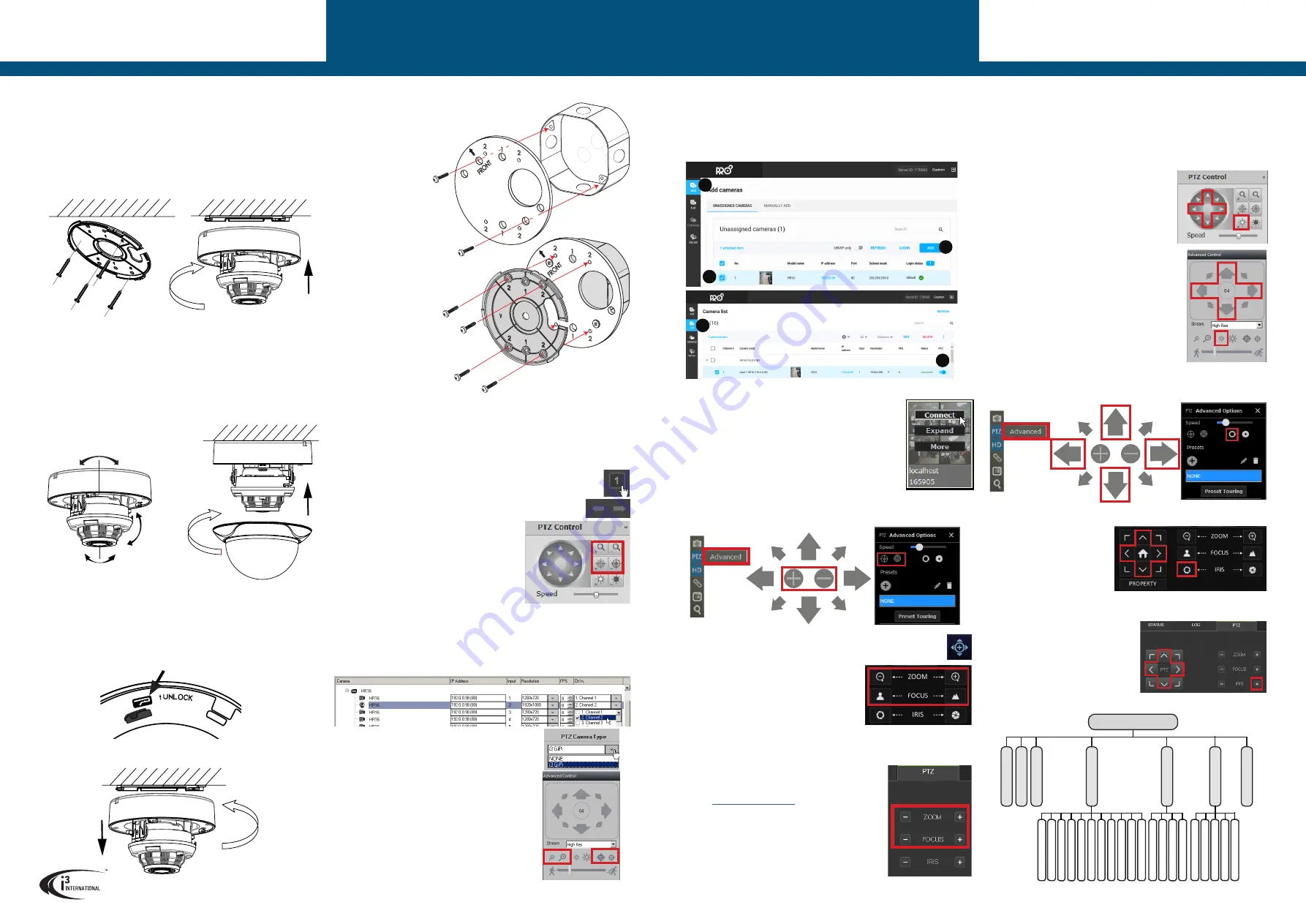
CALLING UP OSD MENU
Camera’s OSD menu can be accessed through i3’s encoder, i3’s standalone HVR’s
local or remote interfaces or through SRX-Pro/VPC interface.
In all cases,
Iris Open
icon in the Live Mode PTZ panel will bring up the camera’s on
screen display.
PTZ panel OSD Menu control buttons:
Iris Open
- Bring up the OSD, confirm menu selection/enter sub-menu.
UP/DOWN arrows
to navigate within camera menus.
LEFT/RIGHT arrows
to adjust value of the selected
item.
CALLING UP OSD via HR16
1.
Repeat Steps 1-8 of the
ADJUST ZOOM/FOCUS
via HR16 section.
2.
Use the
Iris Open
and
UP/DOWN/LEFT/RIGHT
buttons on the PTZ Control panel to bring up and
navigate in the OSD menus.
CALLING UP OSD via SRX-PRO SERVER
v6
and lower
1.
Repeat Steps 1-8 of the
ADJUST ZOOM/FOCUS via
SRX-PRO SERVER v6 and lower section.
2.
Use the
Iris Open
and
UP/DOWN/LEFT/RIGHT
buttons on the Advanced Control panel to bring up
and navigate in the OSD menus.
LENS ADJUSTMENT
Your Am51 camera is equipped with the motorized 2.7-13.5mm lens. To achieve desired
view, start by adjusting the lens angle along the 3 axis by panning/tilting the camera body
and rotating the lens assembly. The lens zoom and focus can be adjusted through i3’s
encoder, i3’s standalone HVR’s local or remote interfaces, through SRX-Pro/VPC interface,
or through HD service monitor with BNC input.
ADJUST ZOOM/FOCUS via HR16
1.
Connect Am51 to HR16.
2.
In Internet Explorer, enter HR16 address. (Default: 192.0.0.16).
3.
Enter user credentials in the Annexxus login screen.
(Default: i3admin/i3admin).
4.
Go to
SETUP > Camera > PTZ Settings
5.
In
Channel No.
, select the HR16 port where Am51
is connected (E.g. Analog Camera 1).
6.
In
PTZ Protocol
, select
i3-HDA
. Click
Save
.
7.
Click
LIVE
to go back to the live mode. Select a
single camera division.
8.
Use Previous/Next buttons to locate desired
Am51 camera.
9.
Use the PTZ Control panel to adjust Zoom and
Focus until the desired view is achieved.
ADJUST ZOOM/FOCUS via SRX-PRO SERVER v6 and lower
1.
Repeat Steps 1-6 of the
ADJUST ZOOM/FOCUS via HR16 section.
2.
Add HR16 to SRX-Pro Server’s IP camera tab.
3.
In IP Camera tab, expand HR16 item to see all inputs. Assign Am51 input to SRX-Pro
Server video channel in
Ch. In.
drop-down menu.
4.
Go to Hardware > Channels setup tab.
5.
Locate the Channel that Am51 was assigned to in the
Step 3 and set
PTZ Camera Type
to
i3 GiPi
.
6.
Click the Live Mode button.
7.
Go to
View > Tree View
and expand Advanced
Control panel.
8.
Double-click on the Am51 camera to bring it into full
single-channel division.
9.
Use the Advanced Control panel to adjust Zoom and
Focus until the desired view is achieved.
REMOVAL
To remove the camera from its mounted position,
1.
Rotate the dome bubble in a counter-clockwise motion and lift it away from the
main camera module.
2.
On the camera module, locate the lock tab marked “UNLOCK”.
3.
Using a long pointed object, such as a flat-head screwdriver press the lock tab
upwards to unlock the camera module from its back plate.
4.
Continue pressing the lock tab pin upwards and rotate the camera module in a
counter-clockwise motion to remove it from the mounted back plate.
ROUND/OCTAGON ELECTRICAL BOX MOUNTING
(Optional B11 mounting plate required)
For electrical box installations, purchase the optional B11
mounting plate.
CALLING UP OSD via VIDEO PILOT CLIENT
(incl. SRX-PRO SERVER v7 and up).
1.
Repeat Steps 1-5 of the
ADJUST ZOOM/FOCUS via
VIDEO PILOT CLIENT (incl. SRX-PRO SERVER v7 and up) section.
2.
Use the
Iris Open
in the PTZ Advanced Options side panel and the on-screen
UP/DOWN/LEFT/RIGHT
buttons to bring up and navigate in the OSD menus.
CALLING UP OSD via VEO16p (LOCAL)
1.
Repeat Steps 1-5 of the
ADJUST ZOOM/FOCUS via
VEO16p (LOCAL) section.
2.
Use the
Iris Open
icon and
the
UP/DOWN/LEFT/RIGHT
buttons on the PTZ panel to
bring up and navigate in the
OSD menus.
CALLING UP OSD via VEO16p (REMOTE)
1.
Repeat Steps 1-7 of the
ADJUST
ZOOM/FOCUS via VEO16p (REMOTE)
section.
2.
Use the
Iris Open
icon and the
UP/
DOWN/LEFT/RIGHT
buttons on the
PTZ panel to bring up and navigate in
the OSD menus.
ADJUST ZOOM/FOCUS via VIDEO PILOT CLIENT
(incl. SRX-PRO SERVER v7 and up)
1.
Repeat Steps 1-5 of the
ADJUST ZOOM/FOCUS via SRX-PRO
SERVER v6 and lower section OR Steps 1-3 of the ADDING
HR16 to SRX-PRO v7 depending on the SRX-Pro Server
version.
2.
Add the SRX-Pro Server to CONTROL tab of the Video Pilot
Client if connecting from a remote location, or use
localhost
connection, automatically generated by VPC.
3.
Connect to the remote SRX-Pro Server with VPC.
4.
Double-click on the Am51 camera to bring it into full single-
channel division.
5.
Click
PTZ > Advanced
in the on-screen menu.
6.
Use the on-screen Zoom In/Out controls and
Focus In/Out controls in the PTZ Advanced Options side panel to adjust Zoom and
Focus until the desired view is achieved.
ADJUST ZOOM/FOCUS via VEO16p(LOCAL)
1.
Connect Am51 to Veo16p BNC output.
2.
Log into your Veo16p (Default: ADMIN/1234).
3.
Go to
MENU > SYSTEM SETUP > CAMERA > PTZ SETUP
4.
In PROTOCOL drop down menu, select
COAXITRON
for all Am51 cameras. Click
APPLY
,
then
CLOSE
.
5.
On the Veo16p Live screen, click the PTZ button to
display PTZ control panel.
6.
Use the ZOOM and FOCUS icons adjust Zoom and
Focus until the desired view is achieved.
ADJUST ZOOM/FOCUS via VEO16p (REMOTE)
1.
Repeat Steps 1-4 of the
ADJUST ZOOM/FOCUS via VEO16p (LOCAL) section.
2.
Connect your Veo16p to the network using the ETHERNET port on the rear panel.
Follow Veo16p manual for more instructions.
3.
On the remote PC, open Internet Explorer and enter the
IP address of your Veo16p in the address bar, followed by
the Web Service Port. Default service port:
8080
.
)
4.
Enter user credentials in the login screen.
(Default: ADMIN/1234).
5.
Install ActiveX, as required.
6.
In the Veo16p Live screen mode, double-click on the
Am51 camera to bring it into full single-channel division.
7.
Click on the PTZ tab and use Use the ZOOM and FOCUS
icons adjust Zoom and Focus until the desired view is
achieved.
SURFACE MOUNTING
(w/o B11 optional mounting plate)
1.
Attach the supplied surface mounting template to the mounting surface.
2.
Drill four holes marked “2” on the template and insert supplied anchors into the
holes.
3.
Drill the conduit hole for the camera cable, as marked on the template.
4.
Use the tapping screws provided (if suitable for the installation) to secure the
camera’s back plate to the prepared mounting surface.
5.
Twist the main camera module onto the mounted camera back plate in a
clockwise motion until it locks into place and an audible click is heard. The
camera is now secured to the mounting surface.
6.
Feed the camera cables through the conduit hole.
3-axis Range Limitations:
Pan:
0 - 340º
Tilt:
0 - 75º
Rotation:
0 - 355º
Press upwards to unlock
7.
Connect camera to DC12V/AC24V power, 9.7W required.
8.
Adjust the lens angle by panning and tilting the camera lens assembly and
rotating the camera lens base. Do not over-rotate beyond the stop point to avoid
damage to the camera.
9.
Adjust the camera’s zoom and focus through a DVR/HVR, encoder, SRX-Pro/VPC
software or HD service monitor with BNC input.
See LENS ADJUSTMENT section for more information.
10.
Adjust any additional camera settings (e.g. image brightness, color or contrast,
day/night mode, etc.).
See CAMERA MENU section for more information on
camera’s on-screen menu.
11.
Once the desired view is achieved, twist the camera’s dome bubble onto the
camera module in a clock-wise motion until it locks into place and an audible
click is heard.
See B11 mounting instructions
for additional information.
1.
Follow DISASSEMBLY
instructions to remove
camera’s back plate.
2.
Attach B11 mounting
plate to the round/octagon
electrical (gang) box
using the middle set of
countersink holes. Use the
2 screws included with
the electrical box.
3.
Secure the camera’s
back plate to the four (4)
threaded holes marked
“2” on the mounted B11
using four (4) machine-
type screws provided
with B11.
4.
Complete the installation
following
Steps #5-11 in the
SURFACE MOUNTING
section.
USER MANUAL
Am51 Analog Dome Camera
Am51 Analog Dome Camera
USER MANUAL
i3 INTERNATIONAL INC.
1.866.840.0004
www.i3international.com
Page -2-
Page -3-
MAIN MENU
CONTRAST
BACK
IMAGE MODE
EXPOSURE
MODE
EXIT
WHITE BALANCE
AGC
BRIGHTNESS
BACK
FA
CT
OR
Y DEF
AUL
T
DA
Y/NIGHT
VIDEO SETTINGS
EXPOSURE
3DNR
EXIT
SHARPNESS
SA
TURA
TION
EXIT
SA
VE & EXIT
MODE
VIDEO FOR
M
AT
SA
VE & EXIT
SA
VE & EXIT
MIRROR
BACK
EXIT
SA
VE & EXIT
ADDING HR16 to SRX-PRO SERVER v7 and up
SRX-Pro v7 users must complete this step before adjusting lens zoom/focus through VPC
v7 and above.
1.
Repeat Steps 1-6 of the
ADJUST ZOOM/FOCUS via HR16 section.
2.
Log into Pro Setup.
3.
Add HR16
i.
Click
Add. ii.
Select HR16 in the list.
iii.
Click
ADD.
iv.
Click
List. v.
Enable
PTZ
toggle for all Am51 inputs on HR16.
i
ii
iii
iv
v
CAMERA OSD MENU


