USER MANUAL
Page -2-
Am73 Analog Dome Camera
LENS ADJUSTMENT
Your Am73 camera is equipped with the motorized 2.7-13.5mm lens. To achieve
desired view, start by adjusting the lens angle along the 3 axis by panning/tilting the
camera body and rotating the lens assembly. The lens zoom and focus can be adjusted
through i3’s encoder, i3’s standalone HVR’s local or remote interfaces, through SRX-
Pro v6/VPC interface, or through HD service monitor with BNC input.
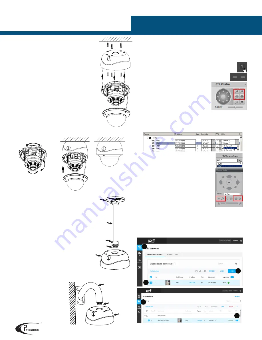
ADJUST ZOOM/FOCUS via HR16
1.
Connect Am73 to HR16.
2.
In Internet Explorer, enter HR16 address. (Default: 192.0.0.16).
3.
Enter user credentials in the Annexxus login screen.
(Default: i3admin/i3admin).
4.
Go to
SETUP > Camera > PTZ Settings
5.
In
Channel No.
, select the HR16 port where
Am73 is
connected (E.g. Analog Camera 1).
6.
In
PTZ Protocol
, select
i3-HDA
. Click
Save
.
7.
Click
LIVE
to go back to the live mode. Select a
single camera division.
8.
Use Previous/Next buttons to locate desired
Am73 camera.
9.
Use the PTZ Control panel to adjust Zoom and
Focus until the desired view is achieved.
ADJUST ZOOM/FOCUS via SRX-PRO SERVER v6 and lower
1.
Repeat Steps 1-6 of the
ADJUST ZOOM/FOCUS via HR16 section.
2.
Add HR16 to SRX-Pro Server’s IP camera tab.
3.
In IP Camera tab, expand HR16 item to see all inputs. Assign Am73 input to SRX-
Pro Server video channel in
Ch. In.
drop-down menu.
1.
Drill the conduit hole for the camera cable, as marked on the
template, if using the top conduit hole to route cables. Skip
this step if using the side conduit hole.
If routing the cable through the side cable exit, remove the
cable exit plug. If mounting on a wall, make sure the opening
is pointing down, to create a drip loop.
Mount the back box
2.
Use the tapping screws provided (if suitable for the
installation) to secure the camera’s back box to the prepared
mounting surface.
Connect camera cables and attach the camera
3.
Feed the camera cables through the selected conduit hole.
4.
Connect camera to DC12V/AC24V power, 8W required.
5.
Connect camera’s BNC connector to the coaxial cable.
6.
Use the supplied security Torx key to attach the camera
module to the back box. Use three long machine-type screws
pre-inserted into the camera module.
Adjust camera view and complete the installation
7.
Adjust the lens angle by panning and tilting the camera
lens assembly and rotating the camera lens base. Do not
over-rotate the camera lens beyond the stop point to avoid
damage to the camera.
8.
Adjust the camera’s zoom and focus through camera’s OSD,
through IE or SRX-Pro.
See LENS ADJUSTMENT section for
more information.
9.
Adjust any additional camera settings (e.g. image brightness,
color or contrast, day/night mode, etc.).
See CAMERA MENU
section for more information on camera’s on-screen menu.
10.
Once the desired view is achieved, replace the camera dome bubble and re-
tighten 3 silver screws securing the dome bubble to the camera base.
4.
Go to Hardware > Channels setup tab.
5.
Locate the Channel that Am73 was assigned to in
the Step 3 and set
PTZ Camera Type
to
i3 GiPi
.
6.
Click the Live Mode button.
7.
Go to
View > Tree View
and expand Advanced
Control panel.
8.
Double-click on the Am73 camera to bring it into
full single-channel division.
9.
Use the Advanced Control panel to adjust Zoom
and Focus until the desired view is achieved.
FLUSH MOUNTING
Am73 camera can be flush mounted with the use of i3’s flush mounting kit
(Part # AM42FM, sold separately). When flush-mounting
the camera, do not use the supplied camera back box.
Follow the mounting instructions supplied with the kit.
WALL MOUNTING
(with optional DB60 gooseneck bracket)
ADDING HR16 to SRX-PRO SERVER v7 and up
SRX-Pro v7 users must complete this step before adjusting
lens zoom/focus through VPC v7 and above.
1.
Repeat Steps 1-6 of the
ADJUST ZOOM/FOCUS via
HR16 section.
2.
Log into Pro Setup
3.
Add HR16
i.
Click
Add.
ii.
Select HR16 in the list.
iii.
Click
ADD.
iv.
Click
List.
v.
Enable
PTZ
toggle for all Am73 inputs on HR16.
i
ii
iii
iv
v
3-axis Range Limitations:
Pan:
0-355°
Tilt:
0-75°
Rotation:
0-355°
Compatible i3 Mounting Accessories:
DB60
- Wall Mount bracket. 3/4” Male. Combine with DB60CPM for
Corner or Pole Mount installations.
Use a 3/4” Electrical EMT Conduit Fitting with a rigid
3/4” pipe for this type of installation.
PENDANT MOUNTING
DB60
Gooseneck
bracket
Use silicone
to maintain
IP66 rating
Am73
back box
Attach the top conduit hole of the camera’s
back box to the threaded end of the 3/4”
Electrical EMT Conduit Fitting and rotate
clockwise to attach the two together.
Use silicone sealer to maintain IP66 rating
when installing outdoors.
Complete installation as for Surface Mounting
from Step #7 onwards.
Floor
flange
3/4” pipe
fitting
Ridgid
3/4” pipe
Use silicone to maintain
IP66 rating
Am73
back box
3/4” Electrical
EMT conduit
fitting
DB60CPM
- Corner/Pole Mount
kit. Combine with DB60 Mount
DB60 gooseneck bracket on the
wall. Follow installation instructions
provided with DB60.
Attach Am73 back box to the DB60
gooseneck bracket.
Complete installation as for Surface
Mounting from Step #7 onwards.


