


USER MANUAL
Page -2-
Am42 Series Analog Dome Camera
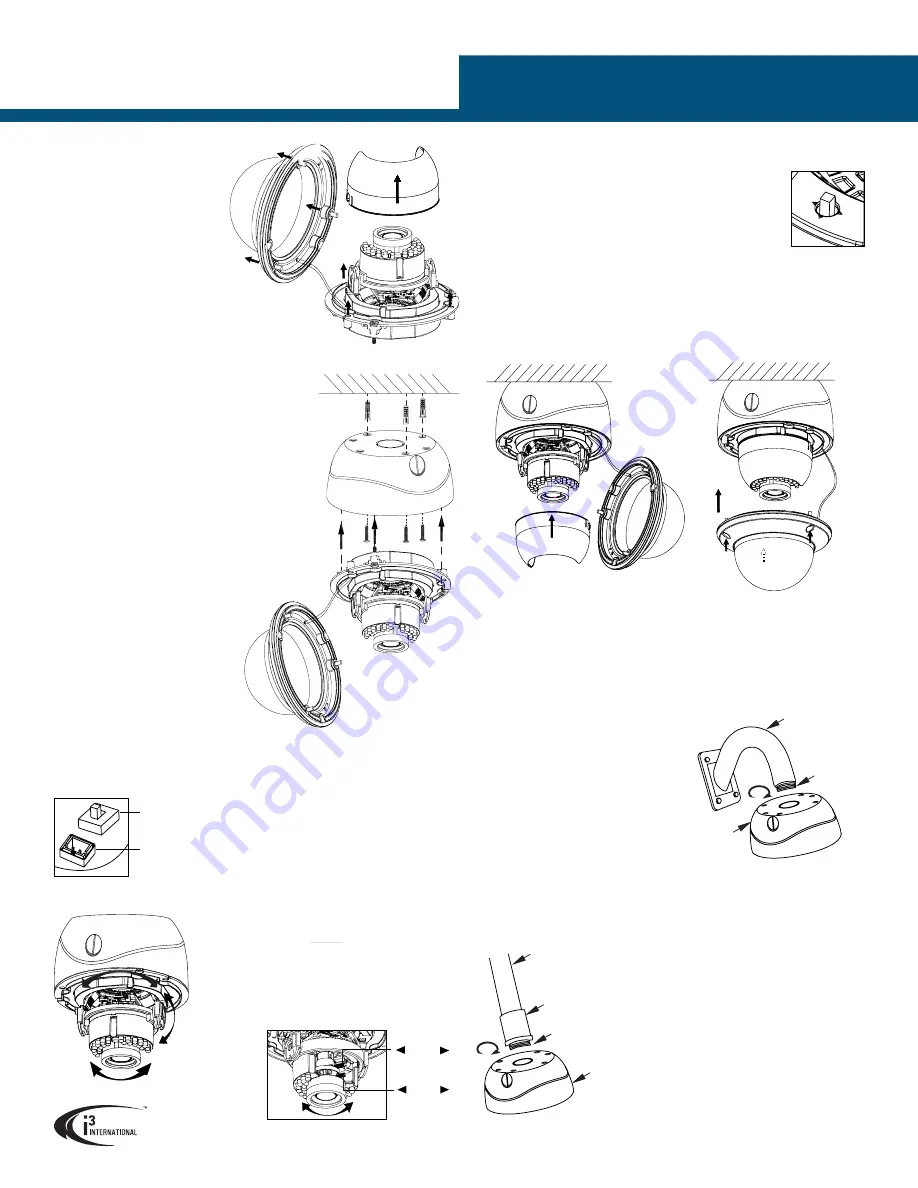
UP
Focus Lever +
locking screw
(Far/Near)
F N
Zoom Lever +
locking screw
(Tele/Wide)
T W
INSTALLING THE CAMERA
Prepare the mounting surface.
• Depending on the type of
installation, additional mounting
accessories may need to be
purchased.
• It is the installer’s responsibility
to ensure that the mounting
surface is suitable for the chosen
installation method.
• Based on installation location and
surface type, supplied screws and anchors
may not be adequate. Mounting hardware
is site-specific and may need to be supplied by the
installer.
SURFACE MOUNTING
1.
Use the supplied security Torx key to loosen three
screws securing the dome bubble housing to camera
module. Gently pull the dome bubble away from the
main camera module.
2.
Temporarily remove the camera liner/shroud for
3-axis Range Limitations:
Pan:
0 - 355°
Tilt:
0 - 75°
Rotation:
0 - 355°
three long machine-type screws pre-inserted
into the camera module.
10.
Connect camera to 12DC or 24AC power
and attach the service monitor to the 2-pin
connector on the camera.
11.
Adjust the lens angle by panning and tilting the
camera lens assembly and rotating the camera
lens base. Do not over-rotate the camera lens
beyond the stop point to avoid damage to the
camera.
CVBS / TVI
dipswitch
2-pin Service
Monitor
connector
13.
Use the joystick on the camera board to adjust any additional camera settings (e.g.
image brightness, colour or contrast, day/night mode, etc.).
See CAMERA MENU
section for more information on camera’s on-screen menu.
Set the video format dip switch to the desired setting:
CVBS
(standard composite video, 720x480) or
TVI
(high-definition video, 1MP). Depending on the dip switch
selection, the matching BNC video connector will be enabled on
the camera.
IMPORTANT:
In order to be able to use high-definition video,
Joystick
your Am42R camera
must be connected to i3’s HR16 video encoder or
standalone Veo17 DVR.
If connecting directly to the HVR’s / DVR’s BNC panel, set the dip switch to CVBS to
camera’s inner liner (shroud) until it snaps back into place.
15.
Replace the camera dome bubble and tighten the 3 silver screws securing the
dome bubble to the camera base.
FLUSH MOUNTING
Am42 Series cameras can be flush mounted with the use of i3’s flush mounting kit
(Part # AM42FM for the AM42R and the AM42FMB for the AM42RB, sold separately).
When flush-mounting the camera, do not use the supplied camera back box.
Follow the mounting instructions supplied with the kit.
WALL MOUNTING w/ GOOSENECK BRACKET
12.
Adjust the camera’s zoom and focus using
Zoom / Focus levers on the camera module.
Loosen the locking screws, adjust the lever
and re-tighten the locking screw when
desired view is achieved.
use 720x480 composite video cable.
14.
Once the desired view is achieved, unplug the service monitor and replace
Am42R
Back Box
DB60
Gooseneck
Bracket
Use silicone
to maintain
IP66 rating
3/4” Rigid
Pipe
3/4” Electrical
EMT Conduit
Fitting
Use silicone
to maintain
IP66 rating
Am42R
Back Box
Am42R camera can be wall-mounted with the
use of i3’s gooseneck wall bracket (Part # DB60
for the Am42R and DB60B for the AM42RB
sold separately). Together with the optional
DB60CPM/DB60CPMB bracket, DB60/DB60B
gooseneck bracket has the capability of being
corner- or pole-mounted.
Follow the mounting instructions supplied
with the DB60/DB60B bracket.
Attach the top conduit hole of the camera’s back
box to the threaded end of the DB60/DB60B bracket and
rotate clockwise to attach the two together. Use silicone sealer to maintain IP66 rating
when installing outdoors.
Complete installation as for Surface Mounting from Step #8 onwards.
PENDANT POLE MOUNTING
Use a 3/4” Electrical EMT Conduit Fitting with a rigid
3/4” pipe for this type of installation.
Attach the top conduit hole of the camera’s back box
to the threaded end of the 3/4” Electrical EMT Conduit
Fitting and rotate clockwise to attach the two
together.
Use silicone sealer to maintain IP66 rating
when installing outdoors.
Complete installation as for Surface Mounting
from Step #8 onwards.
easier lens adjustment.
3.
Depending on the type of installation and mounting
surface, complete drilling 2-4 holes in the back box
in preparation for the mounting.
4.
Attach the supplied mounting template to the
mounting surface.
5.
Drill holes, as marked on the template and insert
supplied anchors into the holes. The number and
positioning of holes must match the ones pre-
drilled on the back box in Step 4.
6.
Drill the conduit hole for the camera
cable, as marked on the template,
if using the top conduit hole to
route cables. Skip this step if
using the side conduit hole.
7.
Use three tapping screws provided
to secure the camera’s back box to
the prepared mounting surface.
8.
Feed the camera cables through the
selected conduit hole. Use silicone sealer
around the chosen conduit hole to maintain IP66 rating when installing the Am42R
outdoors.
9.
Use the supplied security Torx key to attach the camera module to the back box. Use


