background image


i2O 

|

 www.i2owater.com

 |

 [email protected]

 |

 +44 (0) 2380 111 420 

Page 10


iii.


Commissioning procedure 

1.  Ensure the APV is connected to the PRV but with the control space tap either 

shut.  
 

2.  Open the upstream and downstream taps, this will pressurise the i2O APV and 

pipe  work.  Check  for  leaks  on  both  the  hoses  and  the  fittings  at  this  point, 
rectifying or repairing as necessary. 


3.  When you see pressures recorded on the i2O Configurator (“Live Data” Screen) 

that are within acceptable limits for the location, slowly open the control space 
tap.  


4.  The pilot will now take control of the valve and it is likely that some change in the 

downstream 

pressure 

could 

be 

registered 

at 

this 

point.  

Note:  Different  sized valves  can  react  to  changes  in their control  pressures  at 
different speeds, small valves can react almost instantly and can be very variable 
whereas larger valves tend to move more slowly but be more stable.


5.  Allow  the  pressures  to  stabilise  before  making  any  adjustments.  Given  the 

variability of installation, it is possible for set pressures to be +/- 2meters from the 
target  pressure  required.  If  this  occurs,  then  adjust  the  end  cap,  using  the  C 
spanner in the method described earlier, either in a clockwise or anti clockwise 
rotation 

to 

achieve 

the 

target 

start 

pressure. 

Do not change any other settings at this point; only adjust the APV end cap if 
necessary.


6.  At this stage, the pilot will work as a conventional hydraulic pilot and will attempt 

to maintain the set fixed outlet pressure.  


7.  In order for the system to begin controlling, this must be correctly configured in 

oNet,  the  oNet  settings  will  take  effect  the  next  time  the  device  dials  up. 

It  is 

recommended that  the installer forces a  dial-up to check the  behaviour before 
leaving site, as control settings could immediately change pressure

.  


8.  When  active  control  is  implemented  and  the  user  is  satisfied  with  the  correct 

operation of the i2O system, then it is important that service mode is deactivated 
before disconnection of the device from the Configurator.  


Installation  of  the  PRV  Control  System  is  now  complete.  If  you  experience  any 
difficulty  or  require  assistance  at  any  stage  please  email  photographs  of  the 
installation to 

[email protected]

, stating the name and location of the site and 

device serial number. 


Summary of Contents for PRV

Page 1: ... Science Park Southampton SO16 7QJ United Kingdom www i2owater com info i2owater com 44 0 2380 111 420 Company registration no 98345 6784 PRV Control System Installation and Commissioning Manual Author Imran Jones Issue 1 1 Date 19 Apr 2017 ...

Page 2: ...2O kits The installation requires upstream downstream and control space tappings at the PRV with shut off valves fitted to each tapping prior to installation After installation calibration and commissioning the PRV control is adjusted remotely using the i2O Web platform oNet The required profiles can be configured in oNet prior to commissioning and these settings will be applied when the controlle...

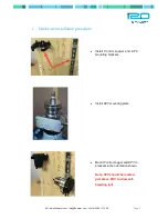
Page 3: ...420 Page 2 i Hardware installation procedure Install Control Logger and APV mounting brackets Install APV mounting plate Mount Control Logger and APV to brackets in the orientation shown Note APV should be located just above PRV to allow self bleeding air ...

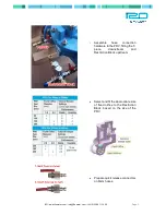
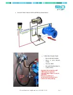
Page 4: ... 3 Assemble hose connection hardware to the PRV fitting the T piece downstream and Restriction Block upstream Select and fit the appropriate size of fixed orifice to the Restriction Block based on the size of the PRV Prepare quick release connectors on 6mm hoses ...

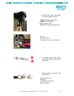
Page 5: ...Upstream pressure P1 GREEN Control Space Pressure Optional P3 BLUE Downstream pressure P2 A Flow B APV PILOT C USB port to connect the Laptop If required splice flow meter cable in accordance with supplied instructions Assemble Serto couplings onto 12mm hoses A Compression nut B Sleeve C Stainless steel insert D Male adapter ...

Page 6: ...hown below 12mm black hoses should Be as short as possible Have a long smooth radius Have no kinks Be routed appropriately to reduce strain Important Note that the APV shaft moves in and out approximately 10mm in normal operation Ensure no rubbing or restriction to the black hose and do not clamp tubing ...

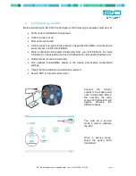
Page 7: ...oad Configurator from your i2O Platform For more information on downloading and using Configurator visit support i2owater com Deploy device through Configurator This updates location DMA details in the device and imports configuration settings Check the flow calibration and adjust as required Ensure PRV is not under i2O control Connect the Control Logger to the Laptop and open Configurator After a...

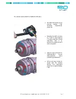
Page 8: ... 18m minimum downstream pressure Rotating the APV end cap by 1 slot is equivalent to 1m water pressure in both directions Use a C spanner to adjust the APV where required Always ensure the APV is depressurized hoses disconnected when performing calibrations When end cap contact is made with the internal spring the equivalent pressure is approximately 10m ...

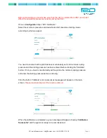
Page 9: ...to ensure that the pilot has been mechanically set to its minimum spring pressure and the starting pressure has been entered before clicking the Calibrate button If not you have to mechanically set the pilot to the minimum spring pressure and enter the starting pressure before continuing Click the button Calibrate and consecutives messages will appear on the main screen Please read carefully all o...

Page 10: ...matically from the starting point configured in the calibration process For this reason it is absolutely vital that the controller is left in service mode when the shut off valves on the PRV are opened to ensure that the APV is still at the same starting point when it starts to hydraulically control the pressure It is only after the pressure has stabilised and the PRV is controlled hydraulically b...

Page 11: ...s to be 2meters from the target pressure required If this occurs then adjust the end cap using the C spanner in the method described earlier either in a clockwise or anti clockwise rotation to achieve the target start pressure Do not change any other settings at this point only adjust the APV end cap if necessary 6 At this stage the pilot will work as a conventional hydraulic pilot and will attemp...

Page 12: ...ent downstream pressure Pressure mH psi bar 4 Adjust APV endcap to set minimum pressure if required Connect to Configurator and carry out APV calibration Record Current downstream pressure Re adjust endcap if necessary Force Dial up from Configurator check pressures and PRV operation Pressure mH bar psi 5 Take photographs of APV to Restriction Block PRV connections If you experience any difficulty...

Reviews: