background image


USER


MANUAL 

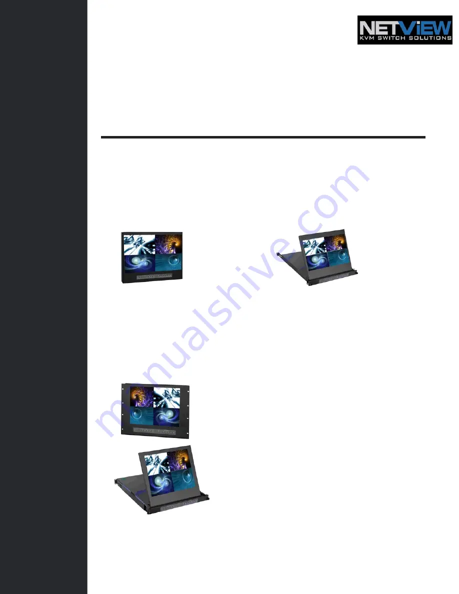
Widescreen LCD Quad Display 

Wide 19”, 22” Screen Size 

Widescreen LCD Quad Display


Models 

NQW922 

NQW819 

4:3 LCD Quad Display 

17", 19", 20" screen size 

4:3 LCD QuaD Display


Models 

NPQ817 / NPQ919 / NPQ1020 


Options

: - DC Power 


Widescreen LCD Drawer


Models 

NQW119 

4:3 LCD Display


Models


NPQ117 / NPQ119 / NPQ120 


Summary of Contents for NPQ1020

Page 1: ...Screen Size Widescreen LCD Quad Display Models NQW922 NQW819 4 3 LCD Quad Display 17 19 20 screen size 4 3 LCD QuaD Display Models NPQ817 NPQ919 NPQ1020 Options DC Power Widescreen LCD Drawer Models...

Page 2: ...n LCD Quad Display Chapter 2 NQW922 NQW819 2 1 Package Contents 5 2 2 Structure Diagram 6 2 3 Installation 7 8 2 4 Connecti on 9 Chapter 3 NQW119 3 1 Package Contents 10 3 2 Structure Diagram 11 3 3 H...

Page 3: ...27 Chapter 8 LCD Specification 28 Chapter 9 Dimensions 29 Chapter 10 Operation 10 1 On screen Display Operation 30 10 2 On screen Menu 31 Chapter 11 Quad Specification 11 1 Basic System Connection 32...

Page 4: ...nction resulting from Accident misuse neglect fire water lightning or other acts of nature unauthorized product modification or failure to follow instructions supplied with the product Repair or attem...

Page 5: ...ou don t intend on using the equipment for a long time disconnect it from the power outlet to prevent being damaged by transient over voltage Keep all liquids away from the equipment to minimize the r...

Page 6: ...direct sunlight away from sources of excessive dust dirt heat water moisture and vibration Convenience for connecting the Rackmount LCD Drawer Display to the related facilities should be well consider...

Page 7: ...8 M218 M0116 M0216 M0316 M1116 M1216 M2116 Matrix DB 15 8 port KVM Matrix IP DB 15 8 port KVM Matrix DB 15 16 port KVM Matrix IP DB 15 16 port KVM Combo Cat6 KVM NVC800 NVCCE800 NVCIP800 NVC1600 NVCCE...

Page 8: ...www iTechKVM com User Manual 2 1 Package Contents Chapter 2 NQW819 NQW922 1 Rackmount LCD display x 1 pc 2 User manual x 1pc 3 6 VGA cable male to male x 1pc 4 Power cord x 1pc 5 Auto switch power ad...

Page 9: ...18 EMAIL info iTechKVM com WEB www iTechKVM com User Manual 2 2 Structure Diagram Chapter 2 1 LCD interchangeable module kit 2 LCD membrane 3 Power adapter bracket RP W719 RP W822 Power adapter bracke...

Page 10: ...L FREE 888 483 2418 EMAIL info iTechKVM com WEB www iTechKVM com User Manual 2 3 Installation Chapter 2 NQW819 Figure 1 Install each screws shown in Figure 1 Figure 2 Fixed the LCD into the rack M6 sc...

Page 11: ...User Manual 2 3 Installation Chapter 2 NQW922 Figure 3 Figure 4 Install each screw shown in Figure 3 M6 screws are not provided Insert the upper part of the LCD display to the rack shown in Figure 4...

Page 12: ...be hot pluggable Plugging and unplugging cables while servers and KVM are powered on may cause irreversible damage to the servers KVM and Rackmount LCD Drawer Before attempting to connect anything to...

Page 13: ...com WEB www iTechKVM com User Manual 3 1 Package Contents Chapter 3 NQW119 1 LCD drawer x 1 pc 2 6 VGA cable male to male x 1pc 3 User manual x 1 pc 4 Power cord x 1 pc 5 Mounting bracket x 2 pcs 6 M6...

Page 14: ...LL FREE 888 483 2418 EMAIL info iTechKVM com WEB www iTechKVM com User Manual 3 2 Structure Diagram Chapter 3 1 LCD interchangeable module kit 3 LCD Quad display membrane 2 One Man Installation Slides...

Page 15: ...mounting rails Adjust the rear mouting bracket to fit your rack M6 screw and cup washer x 6 pcs included Caution Leaving the screws slightly loose until you complete the installation in step Pick up...

Page 16: ...er Manual 3 3 How to Install One Man Installation Slides Chapter 3 Attach front left and right mounting ears of the LCD keyboard drawer to vertical mounting rails M6 screw and cup washer x 2 pcs inclu...

Page 17: ...ck arrow release button is located on the outside of each slide shown in Figure 7 Figure 8 Pull and hold the black arrow button on either side of the LCD keyboard drawer to unlock shown in Figure 10 F...

Page 18: ...and unplugging cables while servers and KVM are powered on may cause irreversible damage to the servers KVM and Rackmount LCD Drawer Before attempting to connect anything to the Rackmount LCD Drawer...

Page 19: ...Type Separate H V Composite SOG 720 x 400 70 Hz 640 x 480 60 70 72 75 Hz 800 x 600 60 70 72 75 Hz 1024 x 768 60 70 75 Hz 1152 x 864 60 70 75 Hz 1280 x 720 60 70 75 Hz 1280 x 720 60 75 Hz 1280 x 1024...

Page 20: ...Dimension W x D x H Net Weight Gross Weight NQW922 500 4 x 70 5mm 19 7 x 2 8 9U 565 x 539 x 156 mm 22 2 x 21 2 x 6 1 12 kg 26 lb 15 kg 33 lb NQW819 480 x 71 5mm 18 9 x 2 8 8U 565 x 495 x 156 mm 22 2...

Page 21: ...TechKVM com User Manual 6 1 Package Contents Chapter 6 NPQ817 NPQ919 RP W1020QD 1 Rackmount LCD display x 1 pc 2 User manual x 1 pc 3 6 VGA cable male to male x 1pc 4 Power cord x 1pc 5 Auto switch po...

Page 22: ...iTechKVM com WEB www iTechKVM com User Manual 6 2 Structure Diagram Chapter 6 1 LCD interchangeable module kit 2 2 in 1 LCD Quad display membrane 3 Power adapter bracket NPQ817 NPQ919 NPQ1020 Power a...

Page 23: ...8 483 2418 EMAIL info iTechKVM com WEB www iTechKVM com User Manual 6 3 Installation Chapter 6 Figure 10 Install each screws shown in Figure 10 Figure 11 Fixed the LCD into the rack M6 screws are not...

Page 24: ...EE 888 483 2418 EMAIL info iTechKVM com WEB www iTechKVM com User Manual 6 3 Installation Chapter 6 NP920 SNP920 Figure 12 Install each screws shown in Figure 12 Figure 13 Fixed the LCD into the rack...

Page 25: ...not be hot pluggable Plugging and unplugging cables while servers and KVM are powered on may cause irreversible damage to the servers KVM and Rackmount LCD Drawer Before attempting to connect anythin...

Page 26: ...7 1 Package Contents Chapter 7 NPQ117 NPQ119 NPQ120 1 LCD drawer x 1 pc 2 6 VGA cable male to male x 1pc 3 User manual x 1 pc 4 Auto switch power adapter for external power version x 1pc 5 Power cord...

Page 27: ...888 483 2418 EMAIL info iTechKVM com WEB www iTechKVM com User Manual 7 2 Structure Diagram Chapter 7 1 LCD interchangeable module kit 3 LCD Quad display membrane 2 One Man Installation Slides 4 Thum...

Page 28: ...mounting rails Adjust the rear mouting bracket to fit your rack M6 screw and cup washer x 6 pcs included Caution Leaving the screws slightly loose until you complete the installation in step Pick up...

Page 29: ...er Manual 7 3 How to Install One Man Installation Slides Chapter 7 Attach front left and right mounting ears of the LCD keyboard drawer to vertical mounting rails M6 screw and cup washer x 2 pcs inclu...

Page 30: ...black arrow release button is located on the outside of each slide shown in Figure 12 Figure 13 Pull and hold the black arrow button on either side of the LCD keyboard drawer to unlock shown in Figure...

Page 31: ...lugging and unplugging cables while servers and KVM are powered on may cause irreversible damage to the servers KVM and Rackmount LCD Drawer Before attempting to connect anything to the Rackmount LCD...

Page 32: ...Analog RGB 0 7Vp p Sync Type Separate H V Composite SOG 720 x 400 70 Hz 640 x 480 60 70 72 75 Hz 640 x 480 60 70 72 75 Hz 800 x 600 60 70 72 75 Hz 1024 x 768 60 70 75 Hz 1152 x 864 60 70 75 Hz 1280 x...

Page 33: ...9U 565 x 495 x 156 mm 22 2 x 19 5 x 6 1 8 kg 18 lb 10 kg 22 lb NPQ1020 series 480 x 71 5 mm 18 9 x 2 8 10U 565 x 539 x 156 mm 22 2 x 21 2 x 6 1 12 kg 26 lb 15 kg 33 lb NPQ117 series 442 x 600 x 44 mm...

Page 34: ...embrane Switch Function Power light Green On Orange Power saving Power on off LCD Display the OSD menu Scrolls through menu options and adjusts the displayed control To auto adjustment by pressing the...

Page 35: ...into the brightness contrast colour temp red green and blue Geometry To enter into the auto adjust H position V position phase and clock Video To enter into the colour tint sharpness noise reduction D...

Page 36: ...or each camera input These switches toggle between 75 and Hi Z impedance Incorrect termination will degrade the quality of the video signal All video inputs not looped through to another device the co...

Page 37: ...m 0 second to 99 minutes for FIO 8037 FIO 8134 through system Setup menu 2 VCR Connection for Tape Recording Start and Stop Control Connecting the contacts of VCR RECORD and STOP switch to the alarm o...

Page 38: ...display a blinking Alarm message Above mentioned alarm can be cleared by If the device is operated under Security Lock ON mode Push Lock button for 2 seconds to disable the function then push any butt...

Page 39: ...i Tech Company LLC TOLL FREE 888 483 2418 EMAIL info iTechKVM com WEB www iTechKVM com User Manual Chapter 11 11 3 Remote Control Connection...

Page 40: ...pin 6 7 8 and 9 must be disconnected to prevent connecting the VCC and GND signals from the device to the computer A RS 232 port only uses pin 1 2 and 3 for control signal transmission 2 A terminal or...

Page 41: ...device has to send out command code H continuously for more than 4 seconds to clear the alarm 3 Setup menu is switched ON by sending VCR DVR and Lock button codes together 4 Text Select and Cursor Co...

Page 42: ...odes that the unit is in Byte two the second 8 bits shows the current status of the alarm operations of the unit BYTE 1 Status code for normal operation modes b7 b6 b5 b4 b3 b2 b1 b0 LOCK VCR SEQU QUA...

Page 43: ...ch channel next 4 bits show the video loss alarm status of each channel The digit 1 means alarm event is detected and 0 means no alarm event is detected b7 b4 Sensor Activated Alarm b3 b0 Video Loss A...

Page 44: ...e 2 of the setup menu Use page 1 to program time date and camera title and page 2 to configure alarm operations Under menu setup mode Channel Select buttons 5 are used for cursor control and text sele...

Page 45: ...nu permits the setup of separate titles for each video channel 8 characters may be entered for each video channel The available alphanumeric characters are 0 1 2 3 4 5 6 7 8 9 A B C D X Y Z space 1 2...

Page 46: ...odel 2 3 Buzzer The device has a build in buzzer to signal a detected alarm through sound User can choose to disable the buzzer by setting it to OFF 2 4 V Loss Alarm This entry is used to enable or di...

Page 47: ...er Quad screen mode push channel select button to freeze each camera input 6 The Full Screen Display Mode 6 1 Push Quad button 4 to OFF to enter Full screen display mode Under this mode you may call u...

Page 48: ...expand the corresponding quadrants of the pre 11 6 Quad Display Specifications Chapter 11 Item Description Model Number QD NTSC QD PAL Number of Color 16 7 M 16 7 M Imaging System NTSC PAL Resolution...

Page 49: ...NQW119 NPQ120 DC Power input Model 12V 24V 48V Input rating Input voltage 12 Volt 24 Volt 48 Volt Input range 9 18V 18 36V 36 75V Input current No load 50 mA 50 mA 50 mA Full load 4950 mA 2450 mA 1220...

Page 50: ...s considered normal The image quality can be improved by adjusting the phase or pixel rate automatically or manually 3 The membrane power light is not ON Press the power On Off on LCD membrane to chec...

Reviews: