background image

iCylinder2 SFT05 - Software 

v1.0 


iTEC


– PORTUGAL 


www.i-tec.com.pt   


4.1.2- Assembly Sequence   

1.The Outside Cylinder Components   

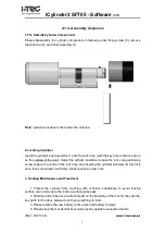
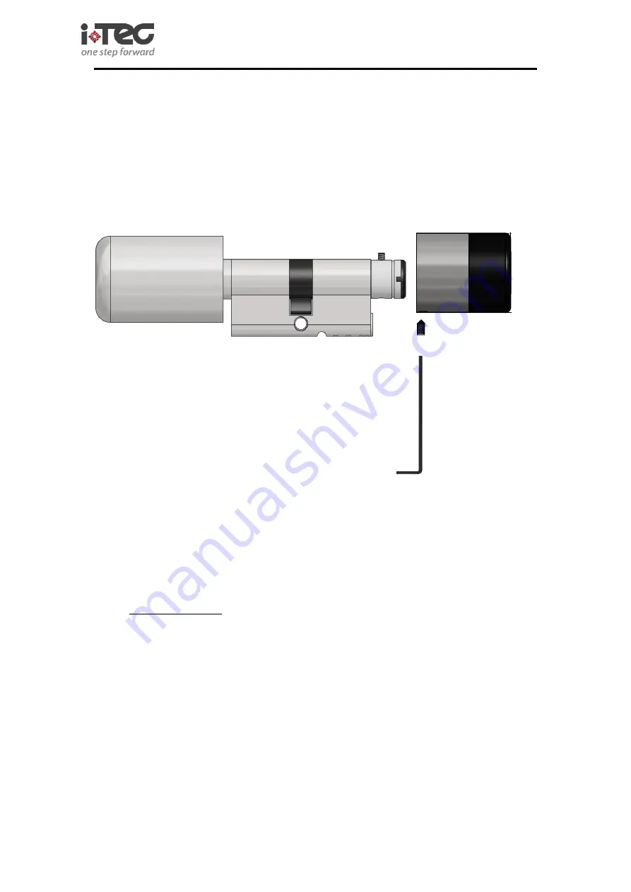
Please disassembly the cylinder components in following order; fixing screw (5), remove 

the Antenna (3), and Inner Assembly (1)   


Note:

 please be caution to take down the antenna.   


2.Locating iCylinder   

Insert the cylinder inner assembly (1) into the lock hole, (with the key hole in the lock pin is 

on the outside of the door). Adjust the cylinder positions to make the lock core positioning 

screw snap to the centre of the lock hole, and inserting the cylinder setscrew (6) into lock 

hole, then screw down it with the cylinder position screw hole.   


3. Routing Maintenance and Treatment   


1.  Protect  the  cylinder  from  touching  with  corrosive  substances  to  avoid  locking 

surface coat, and reduce the locking surface glossiness   

2. Handles and knobs have a direct impact on the flexibility of the lock for they are the 

key parts for the door, please do not hang anything on them.   

3. Please replace the new battery in time when the battery is weak. 

4. Please keep the mechanical keys well properly against unexpected needs. 

Summary of Contents for iCylinder2 SFT05

Page 1: ...iCylinder2 SFT05 Software v1 0 iTEC PORTUGAL www i tec com pt 1 User Manual ...

Page 2: ...s Locks 10 5 3 Handset connect with PC 11 5 4 Handset Language Selection 12 5 5 Update Handset Time 12 5 6 Create a New Project 13 5 7 Create Project Password 13 5 8 Lock Authorization Setting 14 Second Step Edit User Information 14 Third Step Authorization Setting 15 Forth Step Writing the Authorization into Handset 15 Fifth Step Handset Sets Lock Authorization 16 Sixth Step Using card to open do...

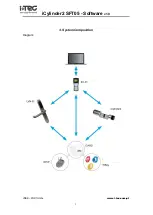
Page 3: ...iCylinder2 SFT05 Software v1 0 iTEC PORTUGAL www i tec com pt 3 3 System Composition Diagram ...

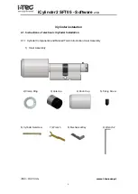
Page 4: ...ylinder instalation 4 1 Instructions of electronic iCylinder Installation 4 1 1 Cylinder Components and Related Tools Introduction Inner Assembly 1 Inner Assembly 2 Clamp Ring 3 Antenna 4 Knob Cap 5 Fixing Screw 6 Cylinder Setscrew 7 Wrench 8 Mechanical Key 9 Wrench 2 ...

Page 5: ...ositions to make the lock core positioning screw snap to the centre of the lock hole and inserting the cylinder setscrew 6 into lock hole then screw down it with the cylinder position screw hole 3 Routing Maintenance and Treatment 1 Protect the cylinder from touching with corrosive substances to avoid locking surface coat and reduce the locking surface glossiness 2 Handles and knobs have a direct ...

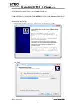
Page 6: ... 2 Instructions of electronic handle LVN01 Installation Please reference to instructions of lock installation in file lock installation instructions 4 3 Software Installation Click SFT05 Office Edition V _Setup files and will appear the following interface Click Next ...

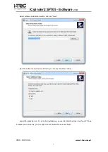
Page 7: ...allation location and click Next Input the software name and click Next you can use the default name Launch the desktop icon if it is the first installation you need to install the driver but if your PC has installed the driver before you can skip the driver installation and click Next ...

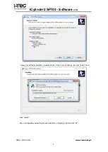
Page 8: ... v1 0 iTEC PORTUGAL www i tec com pt 8 Appear the software installation prepare window if need not any change just click Install is ok Click Install Pop out completed successfully means installation completely and then click ok ...

Page 9: ...iCylinder2 SFT05 Software v1 0 iTEC PORTUGAL www i tec com pt 9 Click Finish mean the software installation completely ...

Page 10: ...nd at this time please press 0 to return the functional button and operation again 5 2 Using Handset Set Lock Room 1 Press 0 for a long time to open the handset then it will show the selection mode in handset LCD if Press 2 the LCD will show 2 1 Update Time 2 2 Read Time 2 3 Config Room No 2 4 Read Room No then please press 3 to select 2 3 Config Room No and input the setting room No then press to...

Page 11: ...C via the USB interface and if driver installation is correct the task bar will shown as following Open the software Office SFT 05 and will appear the following interface PS When the handheld terminal connected with PC successfully The status bar which is in the Lower Right Corner will show Programmer connected in a green word or it will show Programmer disconnected In a red words when connection ...

Page 12: ...e handset time which make the handset time is same with PC current time the specific operation procedure as following shows Step1 Connect the handset and PC via USB Data line then open the system software and click tools to select programmer interface Step2 Click Update to update handset time make which same as PC time Step3 Click Refresh can read handset ID number type current time and other info...

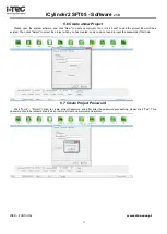
Page 13: ...add the project file which has existed Then click Select to select the project which you has created and you do not need to input the passwords if first time 5 7 Create Project Password Click Tools Project option to create project password and after alter the password successfully please click Yes This password should be remembered if which lost must create new project and system ...

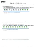
Page 14: ...hich mean to read cylinder information from the handset and then can describe the room information such as general manager office accounting office and so on Second Step Edit User Information Click User to open the user edition windows Put user card on handset inductive area and click Program to read the user card If this card number existed please skip to this card number and describe the card ho...

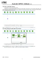
Page 15: ...color means with authorization while white color means without authorization and please set the date and time range and click save to backup the authorization while click delete means delete the authorization and the altered grid will show as blue color Forth Step Writing the Authorization into Handset After altered please click Writing to upload the authorization setting into handset ...

Page 16: ...tion again If connection is successful put the handset on door lock inductive area will communication automatically until operation completely Sixth Step Using card to open door After upload the authorization the card can open the rooms and the specific operation please when reference to Lock Operation Instruction 5 9 Read Lock Records 5 9 1 Collect Event by Handset Press ON OFF for a long time to...

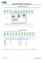
Page 17: ...GAL www i tec com pt 17 5 9 2 Events Upload PC Connect handset with PC via USB data line and open the software please click Reading can collect the cylinder events 5 9 3 Event Inquiry Click event and then inquiry all can see all of the records ...

Page 18: ...s with handset at first time which will bind with each other automatically that is to say other handset can not operate to this lock 5 10 4 Handset Emergency to Open Door Select 4 2 open room can use the banded handset to open the rooms 5 0 5 Prohibiting to Swiping Card Select 4 3 Disable Card can prohibit all of users open the rooms in special situation Note 1 when the cylinder communicates with ...

Reviews: