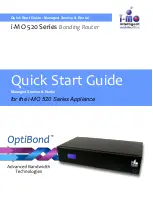
QUICK START GUIDE (Managed Service & Rental) FOR THE EMS I-MO 520 SERIES APPLIANCE
Version
1.2
ELECTRONIC MEDIA SERVICES LIMITED
PASSFIELD BUSINESS CENTRE, LYNCHBOROUGH ROAD, LIPHOOK, HAMPSHIRE, GU30 7SB, UK
Tel:
01428 751655 |
Fax:
01428 751654 |
E-mail:
Page
13
of
18
Appendix B - 3G & 4G Radio Component
Two 3G or 4G radio components may be attached to the i-MO to provide a 3G or 4G signal.
External Aerial Type B
External Aerial Type C
Technical Data
GSM/UMTS Specifications
Frequency ranges:
GSM 850 / 900 MHz 824 - 960 MHz
GSM 1800 MHz 1710 - 1990 MHz
UMTS 2,1 GHz 1900 - 2170 GHz
Gain 5 dBi
Polarization vertical
Rod Length 290mm
Power maximum: 20 W
Cable length 2500 mm
Cable type RG 174
Connector SMA male
VSWR: <= 1.5
Technical Data
GSM/UMTS Specifications
Frequency ranges:
GSM 850 / 900 MHz 824 - 960 MHz
GSM 1800 MHz 1710 - 1990 MHz
UMTS 2,1 GHz 1900 - 2170 GHz
Gain 2.2 dBi
Polarization vertical
Rod Length 240mm
Power maximum: 10 W
Cable length 5000 mm
Cable type RG 58
Connector SMA male
VSWR: 1.5
External Installation
Safety
Installation of this antenna near power lines is dangerous. For your safety, follow these instructions.
Select your installation site with safety, as well as performance in mind. Remember: electric power lines and
phone lines look alike. For your safety, assume that any overhead line can kill you.
When installing your antenna, remember:
Do not use a metal ladder.
Do not work on a wet or windy day.
Do dress properly
—shoes with rubber soles and heels, rubber gloves, long sleeved shirt or jacket.


