DSP-OHMNI Instruction Manual I-GARD
27
In this case there will only be two ‘coils’ (actually DSP functions)
‘Coil’ No
Name
Force Coil Data
00
Reset
ff00 =on
0000=off
01
Pulse
ff00 =on
0000=off
The response of Table 13.4 will confirm the request
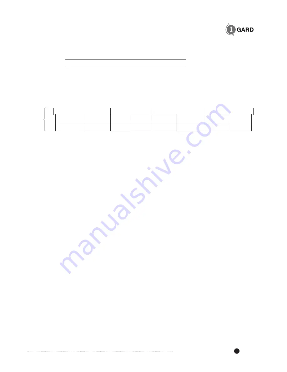
TABLE 13.4 RETURNED INFORMATION FROM DSP FOLLOWING A FORCE BIT REQUEST
Unit I/D
Function
Coil Address
Force Coil
CRC
High
Low
High
Low
High
Low
01
05
00
00
ff
00
nn
nn
Which is just an echo of the request.
The registers can be read either one at a time or in a continuous block up to a maximum of 100
registers at a time.
There are times when the DSP processor will not be able to respond to a request since it is busy
with other tasks and no response will be returned. For this reason it is recommended to request
the maximum number of registers used by the system in a single request. Since the DSP is set
up to 50 current registers, 50 Status registers and 50 Priority registers followed by the System
function registers, it is best to read the data with three consecutive requests.
NOTE
that the DSP will not respond to requests if the DSP-DM is in the SETUP mode.
The Feeder Module currents Igf values are contained in the first 50 registers as follows. The
values range from 0x00 to 0xff although maximum for a first fault condition will be 0x64 or 100%.
Table 13.5 lists the register addresses in the MODBUS convention.


