background image

1-22

R140LC-9, 

R140LC-9, ADJUST

ADJUST BOOM

 BOOM

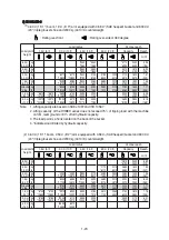
4.90 m (16' 1") adjust boom, 1.90 m (6' 3") arm equipped with 0.58 m

3

 (SAE heaped) bucket and 

600 mm (24") triple grouser shoe and 2000 kg (4410 Ib) counterweight. 

2)

2)

(1)

Â

: Rating over-front

: Rating over-side or 360 degree

Â

Note   1. Lifting capacity are based on SAE J1097 and ISO 10567.
 2. 


Lifting capacity of the ROBEX series does not exceed 75% of tipping load with the machine 
on firm, level ground or 87% of full hydraulic capacity. 


3. The load point is a hook located on the back of the bucket. 


4. *indicates load limited by hydraulic capacity.

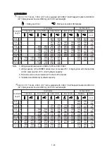
4.90 m (16'  1") adjust boom, 2.10 m (6' 11") arm equipped with 0.58 m

3

 (SAE heaped) bucket and 

600 mm (24") triple grouser shoe and 2000 kg (4410 Ib) counterweight. 

 (2)

Load point 

height

  Load radius

At max. reach

3.0 m (10 ft)

4.5 m (15 ft)

6.0 m (20 ft)

Capacity

Reach

m (ft)

6.0 m

kg

*2900

*2900

*2880

2010

6.45

(20.0 ft)

lb

*6390

*6390

*6350

4430

(21.2)

4.5 m

kg

*3280

*3280

*3150

2220

2530

1540

7.33

(15.0 ft)

lb

*7230

*7230

*6940

4890

5580

3400

(24.0)

3.0 m

kg

*6420

*6420

*4230

3440

3470

2130

2240

1340

7.76

(10.0 ft)

lb

*14150

*14150

*9330

7580

7650

4700

4940

2950

(25.5)

1.5 m

kg

5310

3160

3340

2020

2170

1280

7.84

(5.0 ft)

lb

11710

6970

7360

4450

4780

2820

(25.7)

  Ground

kg

*5430

*5430

5110

2980

3240

1930

2270

1340

7.58

Line

lb

*11970

*11970

11270

6570

7140

4250

5000

2950

(24.9)

-1.5 m

kg

*9210

5620

5050

2940

3220

1900

2630

1570

6.93

 (-5.0 ft) 

lb

*20300

12390

11130

6480

7100

4190

5800

3460

(22.7)

-3.0 m

kg

*8450

5780

5130

3000

(-10 ft)

lb

*18630

12740

11310

6610

Load point 

height

  Load radius

At max. reach

3.0 m (10 ft)

4.5 m (15 ft)

6.0 m (20 ft)

Capacity

Reach

m (ft)

6.0 m

kg

*2690

*2690

*2760

1900

6.68

(20.0 ft)

lb

*5930

*5930

*6080

4190

(21.9)

4.5 m

kg

*3080

*3080

*2990

2230

2420

1470

7.52

(15.0 ft)

lb

*6790

*6790

*6590

4920

5340

3240

(24.7)

3.0 m

kg

*5930

*5930

*4030

3460

*3360

2140

2150

1280

7.94

(10.0 ft)

lb

*13070

*13070

*8880

7630

*7410

4720

4740

2820

(26.0)

1.5 m

kg

*5140

3160

3340

2010

2080

1220

8.02

(5.0 ft)

lb

*11330

6970

7360

4430

4590

2690

(26.3)

  Ground

kg

*5690

5540

5090

2960

3230

1910

2170

1270

7.77

Line

lb

*12540

12210

11220

6530

7120

4210

4780

2800

(25.5)

-1.5 m

kg

*8930

5560

5020

2900

3190

1870

2490

1470

7.14

 (-5.0 ft) 

lb

*19690

12260

11070

6390

7030

4120

5490

3240

(23.4)

-3.0 m

kg

*8650

5690

5070

2950

(-10 ft)

lb

*19070

12540

11180

6500

Summary of Contents for Robex 140LC-9

Page 1: ...Robex 140LC 9 CRAWLER EXCAVATOR SERVICE MANUAL ...

Page 2: ...nction 59 Group 2 Main Control Valve 72 1 Structure 72 2 Hydraulic Circuit 74 3 Function 75 Group 3 Swing Device 99 1 Structure 99 2 Principle Of Driving 102 Group 4 Travel Device 111 1 Construction 111 Group 5 Rcv Lever 121 1 Structure 121 2 Functions 124 Group 6 Rcv Pedal 128 1 Structure 128 2 Function 130 SECTION 3 HYDRAULIC SYSTEM 134 Group 1 Hydraulic Circuit 135 Group 2 Main Circuit 136 1 Su...

Page 3: ...m Up Operation 160 3 Combined Swing And Arm Operation 161 4 Combined Swing And Bucket Operation 162 5 Combined Swing And Travel Operation 163 6 Combined Boom And Travel Operation 164 7 Combined Arm And Travel Operation 165 8 Combined Bucket And Travel Operation 166 SECTION 4 ELECTRICAL SYSTEM 167 Group 1 Component Location 168 1 Location 1 168 2 Location 2 169 Memorandum 172 1 Power Circuit 173 2 ...

Page 4: ...Self diagnostic System 233 3 Machine Error Codes Table 234 4 Engine Fault Code 237 Group 12 Engine Control System 239 1 Mcu And Engine Ecm electronic Control Module 239 2 Mcu Assembly 239 Group 13 Eppr Valve 240 1 Pump Eppr Valve 240 2 Boom Priority Eppr Valve 243 Group 14 Monitoring System 245 1 Outline 245 2 Cluster 245 3 Cluster Connector 247 Group 15 Fuel Warmer System 268 1 Specification 268 ...

Page 5: ...06 15 When Starting Switch Is Turned On Head Lamp Does Not Lights Up 307 16 When Starting Switch Is Turned On Work Lamp Does Not Lights Up 308 Group 4 Mechatronics Systegroup System 309 1 All Actuators Speed Are Slow 309 2 Engine Stall 311 3 Malfunction Of Cluster Or Mode Selection System 313 4 Malfunction Of Accel Dial 314 5 Auto Decel System Does Not Work 316 6 Malfunction Of Pump 1 Pressure Sen...

Page 6: ...1 2 Main Pump 1 2 383 3 Regulator 392 Group 4 Main Control Valve 403 1 Removal And Install Of Motor 403 2 Structure 1 4 404 3 Disassembly And Assembly 408 Group 5 Swing Device 417 1 Removal And Install Of Motor 417 2 Disassembly And Assembly Of Swing Motor 418 3 Removal And Install Of Reduction Gear 429 4 Disassembly And Assembly Of Reduction Gear 430 Group 6 Travel Device 438 1 Removal And Instal...

Page 7: ...tem 521 1 Engine And Accessories Mounting 521 2 Cooling System And Fuel Tank Mounting 522 Group 3 Electric System 523 1 Electric Components Mounting 1 523 2 Electric Components Mounting 2 524 Group 4 Hydraulic System 525 1 Hydraulic Components Mounting 1 525 2 Hydraulic Components Mounting 2 526 3 Hydraulic Components Mounting 3 527 Group 5 Undercarriage 528 Group 6 Structure 529 1 Cab And Accesso...

Page 8: ...Find manuals at https best manuals com ...

Page 9: ...Find manuals at https best manuals com ...

Page 10: ...Find manuals at https best manuals com ...

Page 11: ......

Page 12: ......

Page 13: ......

Page 14: ......

Page 15: ......

Page 16: ...SECTION 1 GENERAL SECTION 1 GENERAL Group 1 Safety Hints 1 1 Group 2 Specifications 1 10 ...

Page 17: ...e excavator attach a ÖDo Not Operate Do Not Operate tag on the right side control lever USE HANDHOLDS AND STEPS USE HANDHOLDS AND STEPS Falling is one of the major causes of personal injury When you get on and off the machine always maintain a three point contact with the steps and handrails and face the machine Do not use any controls as handholds Never jump on or off the machine Never mount or d...

Page 18: ...s Wear goggles or safety glasses PROTECT AGAINST NOISE PROTECT AGAINST NOISE Prolonged exposure to loud noise can cause impairment or loss of hearing Wear a suitable hearing protective device such as earmuffs or earplugs to protect against objectionable or uncomfortable loud noises AVOID POWER LINES AVOID POWER LINES Serious injury or death can result from contact with electric lines Never move an...

Page 19: ...tor starts to move Use a signal person when moving swinging or operating the machine in congested areas Coordinate hand signals before starting the excavator OPERATE ONLY FORM OPERATOR S SEAT OPERATE ONLY FORM OPERATOR S SEAT Avoid possible injury machine damage Do not start engine by shorting across starter terminals NEVER start engine while standing on ground Start engine only from operator s se...

Page 20: ...SYSTEM SAFELY Explosive release of fluids from pressurized cooling system can cause serious burns Shut off engine Only remove filler cap when cool enough to touch with bare hands HANDLE FLUIDS SAFELY AVOID FIRES HANDLE FLUIDS SAFELY AVOID FIRES Handle fuel with care It is highly flammable Do not refuel the machine while smoking or when near open flame or sparks Always stop engine before refueling ...

Page 21: ...ide or in a well ventilated area Dispose of paint and solvent properly Remove paint before welding or heating  If you sand or grind paint avoid breathing the dust Wear an approved respirator ÂIf you use solvent or paint stripper remove stripper with soap and water before welding Remove solvent or paint stripper containers and other flammable material from area Allow fumes to disperse at least 15 ...

Page 22: ... serious injury To prevent accidents use care when working around rotating parts AVOID HIGH PRESSURE FLUIDS AVOID HIGH PRESSURE FLUIDS Escaping fluid under pressure can penetrate the skin causing serious injury Avoid the hazard by relieving pressure before disconnecting hydraulic or other lines Tighten all connections before applying pressure Search for leaks with a piece of cardboard Protect hand...

Page 23: ...le materials Pressurized lines can be accidentally cut when heat goes beyond the immediate flame area Install fire resisting guards to protect hoses or other materials PREVENT BATTERY EXPLOSIONS PREVENT BATTERY EXPLOSIONS Keep sparks lighted matches and flame away from the top of battery Battery gas can explode Never check battery charge by placing a metal object across the posts Use a volt meter ...

Page 24: ...r lime to help neutralize the acid 3 Flush your eyes with water for 10 15 minutes Get medical attention immediate ly If acid is swallowed 1 Drink large amounts of water or milk 2 Then drink milk of magnesia beaten eggs or vegetable oil 3 Get medical attention immediately 13031GE22 USE TOOLS PROPERLY USE TOOLS PROPERLY Use tools appropriate to the work Makeshift tools parts and procedures can creat...

Page 25: ...em DO NOT pour oil into the ground down a drain or into a stream pond or lake Observe relevant environmental protection regulations when disposing of oil fuel coolant brake fluid filters batteries and other harmful waste REPLACE SAFETY SIGNS REPLACE SAFETY SIGNS Replace missing or damaged safety signs See the machine operator s manual for correct safety sign placement LIVE WITH SAFETY LIVE WITH SA...

Page 26: ...eight Muffler Cab Boom cylinder Boom Arm cylinder Arm Track Bucket cylinder Side cutter Control link Control rod Track roller Idler Carrier roller Dozer blade cylinder Dozer blade Main control valve Tool box Fuel tank Hydraulic tank Main pump Tooth Turning joint Swing motor Engine Radiator Oil cooler Bucket 14092SP01 ...

Page 27: ...verall height of cab E 2860 9 4 Ground clearance of counterweight F 940 3 1 Engine cover height G 2050 6 7 Minimum ground clearance H 440 1 5 Rear end distance I 2330 7 7 Rear end swing radius I 2330 7 7 Distance between tumblers J 3000 9 10 Undercarriage length K 3750 12 4 Undercarriage width L 2600 8 6 Track gauge M 2000 6 7 Track shoe width standard N 600 24 Travel speed low high km hr mph 3 6 ...

Page 28: ...idth D 2500 8 2 Overall height of cab E 2860 9 4 Ground clearance of counterweight F 940 3 1 Engine cover height G 2050 6 7 Minimum ground clearance H 440 1 5 Rear end distance I 2330 7 7 Rear end swing radius I 2330 7 7 Distance between tumblers J 3000 9 10 Undercarriage length K 3750 12 4 Undercarriage width L 2600 8 6 Track gauge M 2000 6 7 Track shoe width standard N 600 24 Travel speed low hi...

Page 29: ...1 Engine cover height G 2050 6 7 Minimum ground clearance H 440 1 5 Rear end distance I 2330 7 7 Rear end swing radius I 2330 7 7 Distance between tumblers J 3000 9 10 Undercarriage length K 3750 12 4 Undercarriage width L 2600 8 6 Track gauge M 2000 6 7 Track shoe width standard N 600 24 Height of blade O 550 1 8 Ground clearance of blade up P 560 1 8 Depth of blade down Q 500 1 6 Travel speed lo...

Page 30: ... 10 2 Ground clearance of counterweight F 1200 3 9 Engine cover height G 2310 7 6 Minimum ground clearance H 600 2 0 Rear end distance I 2330 7 7 Rear end swing radius I 2330 7 7 Distance between tumblers J 3030 9 6 Undercarriage length K 3860 12 8 Undercarriage width L 2840 9 4 Track gauge M 2040 6 8 Track shoe width standard N 800 32 Travel speed low high km hr mph 3 6 5 6 2 2 3 5 Swing speed rp...

Page 31: ... mm 28 10 Max dumping height E 5670 mm 18 7 5750 mm 18 10 6060 mm 19 11 6330 mm 20 9 Min swing radius F 2630 mm 8 8 2670 mm 8 9 2650 mm 8 8 2680 mm 8 10 Bucket digging force SAE 87 3 94 8 kN 87 3 94 8 kN 87 3 94 8 kN 87 3 94 8 kN 8900 9660 kgf 8900 9660 kgf 8900 9660 kgf 8900 9660 kgf 19620 21300 lbf 19620 21300 lbf 19620 21300 lbf 19620 21300 lbf ISO 102 110 8 kN 102 110 8 kN 102 110 8 kN 102 110...

Page 32: ...epth C 4240 mm 13 11 4350 mm 14 3 Max digging height D 7700 mm 25 3 7770 mm 25 6 Max dumping height E 5260 mm 17 3 5340 mm 17 6 Min swing radius F 2350 mm 7 9 2460 mm 8 1 Bucket digging force SAE 87 3 94 8 kN 87 3 94 8 kN 8900 9660 kgf 8900 9660 kgf 19620 21300 lbf 19620 21300 lbf ISO 102 110 8 kN 102 110 8 kN 10400 11290 kgf 10400 11290 kgf 22930 24890 lbf 22930 24890 lbf Arm crowd force SAE 76 5...

Page 33: ...11 8890 mm 29 2 9270 mm 30 5 Max dumping height E 6330 mm 20 9 6410 mm 21 0 6780 mm 22 3 Min swing radius F 2670 mm 8 9 2830 mm 9 3 2690 mm 8 10 Bucket digging force SAE 87 3 94 8 kN 87 3 94 8 kN 87 3 94 8 kN 8900 9660 kgf 8900 9660 kgf 8900 9660 kgf 19620 21300 lbf 19620 21300 lbf 19620 21300 lbf ISO 102 110 8 kN 102 110 8 kN 102 110 8 kN 10400 11290 kgf 10400 11290 kgf 10400 11290 kgf 22930 2489...

Page 34: ...eight E 5930 mm 19 5 6010 mm 19 8 6320 mm 20 9 6590 mm 21 7 Min swing radius F 2630 mm 8 8 2670 mm 8 9 2650 mm 8 8 2680 mm 8 10 Bucket digging force SAE 87 3 94 8 kN 87 3 94 8 kN 87 3 94 8 kN 87 3 94 8 kN 8900 9660 kgf 8900 9660 kgf 8900 9660 kgf 8900 9660 kgf 19620 21300 lbf 19620 21300 lbf 19620 21300 lbf 19620 21300 lbf ISO 102 110 8 kN 102 110 8 kN 102 110 8 kN 102 110 8 kN 10400 11290 kgf 104...

Page 35: ... frame weld assembly 1590 3510 1840 4060 Swing bearing 190 410 ą Travel motor assembly 480 1060 ą Turning joint 50 110 ą Track recoil spring 210 460 ą Idler 250 550 ą Carrier roller 40 90 ą Track roller 490 1080 ą Track chain assembly 600 mm standard triple grouser shoe 1010 2230 ą Dozer blade assembly 550 1220 Front attachment assembly 4 6 m boom 2 5 m arm 0 58 m3 SAE heaped bucket 2420 5330 ą 4 ...

Page 36: ...ame weld assembly 2180 4810 Swing bearing 190 410 Travel motor assembly 305 670 Turning joint 50 110 Tension cylinder assembly 280 620 Idler assembly 320 710 Carrier roller assembly 200 440 Track roller assembly 700 1540 Track chain assembly 800 mm standard triple grouser shoe 1370 3020 Front attachment assembly 4 6 m boom 2 5 m arm 0 58 m3 SAE heaped bucket 2420 5330 4 6 m boom assembly 830 1830 ...

Page 37: ...80 2070 2100 1250 8 03 5 0 ft lb 17700 13760 11050 7280 7450 4560 4630 2760 26 3 Ground kg 8780 5800 5200 3090 3270 1970 2180 1300 7 77 Line lb 19360 12790 11460 6810 7210 4340 4810 2870 25 5 1 5 m kg 5740 5740 9910 5700 5080 2990 3220 1920 2500 1500 7 15 5 0 ft lb 12650 12650 21850 12570 11200 6590 7100 4230 5510 3310 23 5 3 0 m kg 8760 8760 9040 5770 5100 3000 3340 2030 6 01 10 ft lb 19310 19310...

Page 38: ...40 3470 2130 2240 1340 7 76 10 0 ft lb 14150 14150 9330 7580 7650 4700 4940 2950 25 5 1 5 m kg 5310 3160 3340 2020 2170 1280 7 84 5 0 ft lb 11710 6970 7360 4450 4780 2820 25 7 Ground kg 5430 5430 5110 2980 3240 1930 2270 1340 7 58 Line lb 11970 11970 11270 6570 7140 4250 5000 2950 24 9 1 5 m kg 9210 5620 5050 2940 3220 1900 2630 1570 6 93 5 0 ft lb 20300 12390 11130 6480 7100 4190 5800 3460 22 7 3...

Page 39: ...680 2210 2610 1550 7 45 5 0 ft lb 18720 14070 12170 7630 8110 4870 5750 3420 24 4 Ground kg 8230 6130 5650 3290 3590 2130 2750 1630 7 17 Line lb 18140 13510 12460 7250 7910 4700 6060 3590 23 5 1 5 m kg 6670 6670 9690 6140 5590 3240 3230 1930 6 48 5 0 ft lb 14700 14700 21360 13540 12320 7140 7120 4250 21 3 3 0 m kg 10970 10970 8330 6270 5520 3300 3690 2830 5 15 10 ft lb 24180 24180 18360 13820 1217...

Page 40: ...10 24 3 1 5 m kg 7800 7120 5680 3850 3930 2480 2820 1770 7 43 5 0 ft lb 17200 15700 12520 8490 8660 5470 6220 3900 24 4 Ground kg 8700 6940 6050 3700 3850 2410 3020 1890 7 09 Line lb 19180 15300 13340 8160 8490 5310 6660 4170 23 3 1 5 m kg 7330 7330 9540 6960 6010 3670 3630 2290 6 31 5 0 ft lb 16160 16160 21030 15340 13250 8090 8000 5050 20 7 3 0 m kg 7950 7130 5200 3760 10 ft lb 17530 15720 11460...

Page 41: ...This as a preview PDF file from best manuals com Download full PDF manual at best manuals com ...

Reviews: