background image

5

Connection

Connection

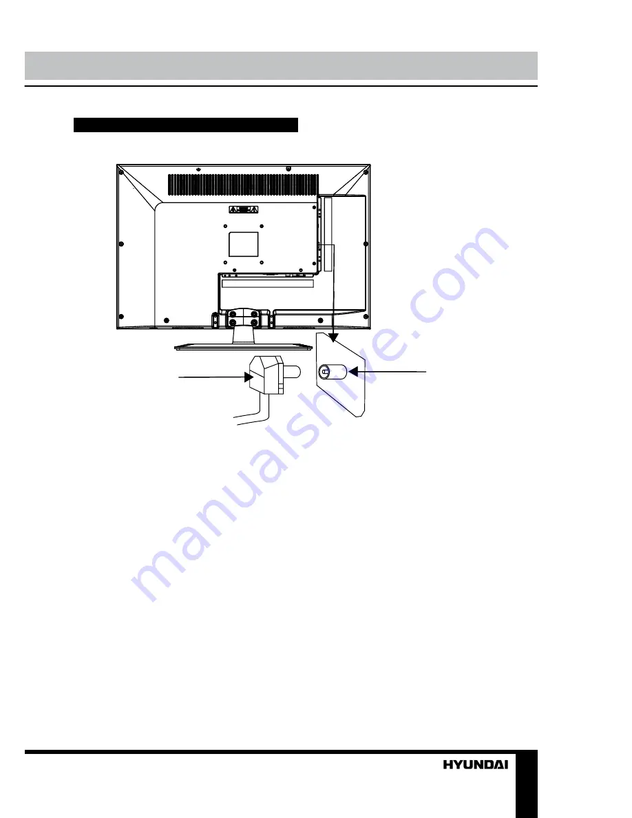
Outdoor Antenna Connection

Use 75

Ω 

coaxial cable plug or 300-75

Ω 

impedance converter to plug in antenna input 
terminal on the rear of the cabinet.

Other connections

•  Connect a TV or CATV antenna to the 

antenna jack.

•  Connect a video source to the Composite 

video input jack with RCA cable.

•  Connect an audio source to the proper 

Audio input jacks (left and right).

•  When using the unit as a computer screen, 

connect the PC to the PC jack of the unit by 
the relevant cable.

•  Connect PC audio input to PC main unit 

with related audio cable in PC mode.

•  If the video source has a HDMI output 

jack, you can connect the signal to the unit by 
HDMI cable (not included).

•  Component input YUV is intended to re-

ceive component video signal from the external 
device. Connection is made with the help of 
supplied YUV connection cable. To receive 
audio signal for component video, please use 
Left and Right audio inputs of this unit.

•  Connect your headphones or earphones 

(not included) to the headphone socket of 
this unit. When earphones are connected, the 
sound output through the built-in speakers of 
this unit is mute.

75 Ohm co-axis cable

TVRF antenna jack

Antenna cable connector

Summary of Contents for H-LED24V14

Page 1: ...www sotmarket ru Hyundai H LED24V14 8 800 775 98 98...

Page 2: ...LED TV Instruction manual H LED24V14 LCD...

Page 3: ...n Channel setting Picture setting Sound setting Timer setting Option setting USB operation Background information Operatoins of file playback General information Troubleshooting Causes of interference...

Page 4: ...t touch the metal part and do not destroy refit twist pull or roast the power cord Please contact the service center immediately if you found that the core is showed in the air or has been broken Plea...

Page 5: ...lling this product If it moves or is tipped over it may be damaged Do not place any fire source such as candlelight close to this product or place it on this product If it is tipped over or fallen dow...

Page 6: ...onnect PC audio input to PC main unit with related audio cable in PC mode If the video source has a HDMI output jack you can connect the signal to the unit by HDMI cable not included Component input Y...

Page 7: ...tons 2 VOL VOL button 3 MENU button 4 SOURCE button 5 POWER button 6 HDMI input 7 Power cord 8 PC VGA input 9 PC audio input 10 Composite video input 11 Stereo audio input 12 Component video input YPb...

Page 8: ...button button 23 Blue button button 24 E W button 25 SUBPAGE button Changing the battery 1 Remove the battery compartment cover on the back of the RC 2 Insert the batteries into the battery compartme...

Page 9: ...nnel number from 1 to 235 directly Press RECALL button on the RC to select from the present channel and the previously displayed channel Press button to display the Favourite channel list in TV mode y...

Page 10: ...e TV channels in whatever order you need Program Edit this item allows you to sort TV programs according to your preferences Enter into program edit menu Delete Select the channel you want to delete P...

Page 11: ...the same level of volume if you change programmes Because each broadcasting station has its own signal conditions volume adjustment may be needed every time when the channel is changed This feature a...

Page 12: ...his value as well as defective USB drives may cause mechanical or thermal changes of elements of this unit as well as failure of internal elements of the USB port Such damages are not warrantee cases...

Page 13: ...e Plug the power cord in Alter the value of contrast brightness color and volume Picture and sound with abnormity Contrast and color are set improperly Color system is set improperly Sound system is s...

Page 14: ...eration of diathermy equipment from a nearby doctor s surgery or hospital SNOW Weak TV signals from long distant stations result in an instead picture and give the effect of falling snow An antenna ad...

Page 15: ...al voltage range of the LED TV 100 240 V 50 60 Hz Power consumption of the LED TV 35 W Power consumption in standby mode less than 1 W Unit dimensions with stand 576 x 178 x 413 mm without stand 576 x...

Page 16: ...14 USB 14 15 15 15 17 17 17 18 18 18 18 19 19 19 19 20 20 21 21 21 21 22 22 23 23 24 24 25 25 25 26 26 26 27 28 15...

Page 17: ...15 220 16...

Page 18: ...16 LCD 10 18 2 17...

Page 19: ...17 4 4 75 18...

Page 20: ...18 75 RCA VGA VGA PC HDMI HDMI HDMI YUV YUV 75 19...

Page 21: ...19 1 2 1 2 1 CH CH 2 VOL VOL 3 MENU 4 SOURCE 5 POWER 6 HDMI 7 8 PC VGA 9 10 11 12 YPbPr 13 14 15 USB 1 2 3 4 5 6 7 8 9 10 11 12 13 14 15 20...

Page 22: ...19 21 20 22 23 24 25 1 POWER 2 3 SOURCE REVEAL 4 SIZE ZOOM 5 MENU 6 ENTER 7 VOL VOL 8 SLEEP 9 REPEAT 1 2 3 10 11 12 TEXT 13 HOLD STILL 14 INFO INDEX 15 16 AUDIO 17 RECALL 18 EXIT 19 CH CH 20 CANCEL 21...

Page 23: ...POWER 5 PC 30 VOL VOL SLEEP 240 SLEEP AUDIO TV Stereo Mono Dual I Dual II Dual I II SOURCE TV Component PC HDMI USB AV TV CH CH 0 9 1 235 RECALL INFO ZOOM 4 3 14 9 16 9 1 2 TEXT TEXT HOLD INDEX SIZE R...

Page 24: ...22 SUBPAGE 0001 SUBPAGE CANCEL E W 1 MENU 2 VOL ENTER SOURCE 3 CH 4 VOL CH 5 MENU EXIT ENTER MENU ENTER PAL SECAM NTSC BG DK I M ATV 23...

Page 25: ...23 ENTER MENU NTSC 4 3 14 9 16 9 1 2 PC RGB 1024x768 60 Hz ENTER MENU 24...

Page 26: ...24 ENTER MENU USB USB USB ENTER MENU 5 25...

Page 27: ...VOB WMV V9 DIVX H263 MPEG 4 MPEGII XVID PCM WAV WMA MP3 DD AC3 1280x720 USB USB 2 0 500 NTFS FAT16 FAT32 USB 5 500 USB USB 1 1 2 0 USB 500 USB USB USB USB BIN USB USB USB ENTER VOL VOL USB ENTER ENTER...

Page 28: ...26 REPEAT H CH EXIT VGA 27...

Page 29: ...27 1 1 2 1 3 2 4 1 5 3 7 YUV 1 8 1 9 1 10 1 28...

Page 30: ...28 24 60 8 5 1366 x 768 16 9 PAL SECAM B G DK I NICAM 2 x 2 RCA USB VGA HDMI 3D 235 1000 USB II 100 240 50 60 35 1 576 x 178 x 413 576 x 41 x 366 4 2 5 H LED22V14_IM_01 29...

Page 31: ......

Page 32: ...2 Hyundai H LED24V14...

Reviews: