background image

< RS232C COMMAND SPEC >

1. CONFIGURATION

1) SPEED : 9600 Baud/s, 8 bit, No parity, 1 Stop bit.
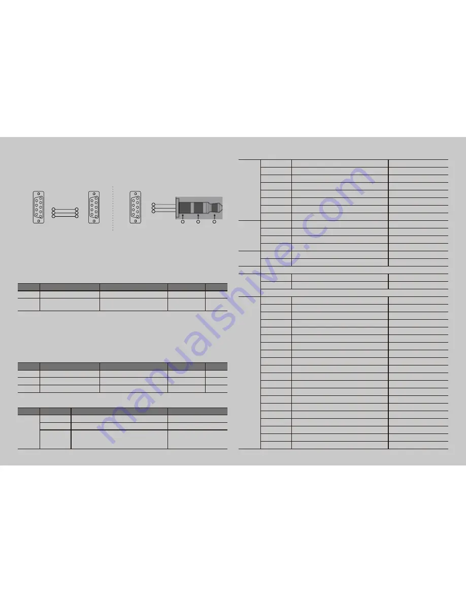
2) Cable Connection

2. COMMAND FORMAT

-  SET ID must select from the OSD menu and can’t be select through the COMMAND. 
-  Only one unit can be set as Master unit, select Master ON from the OSD Menu. (DEFAULT OFF)
-  For viewing COMMAND from Hyper Terminal windows, One unit must set as MASTER ON

1) Data Format

Item

HEADER

SET ID

COMMAND

END

askii

did:

xxx- or all-

follow 2.2

.

hexa

0x64 0x69 0x64 0x3A

0x78 0x78 0x78 0x2D or 0x61 

0x6C 0x6C 0x2D

follow 2.2

0x2E


HEADER : Command head code.


SET ID : Set ID.

all unit control - “xxx- or all-”
unit no : “01 ~ 99”


COMMAND : follow 2.2


END : inform end of send data.

Example. 1 To power on Set ID No 1

Item

HEADER

SET ID

COMMAND

END

askii

did:

01-

pn

.

hexa

0x64 0x69 0x64 0x3A

0x30 0x31 0x2D

0x70 0x6E

WŸYl

decimal

100 105 100 58

48 49 45

112 110

[]

2) Command Type

Item

Command

Description

hexa

Power

pn

power on

WŸ^WGWŸ]l

pf

power off

WŸ^WGWŸ]]

ps

on, video out / on, video in / 
off, video out / off, video in / 
on, dpms mode

WŸ^WGWŸ^Z

Input - 
Source

sd

input hdmi

0x73 0x64

sv

input dvi

0x73 0x76

sp

input pc

0x73 0x70

sc

input component

0x73 0x63

sa

input av

0x73 0x61

sdp

input Droid PC

0x73 0x64 0x70

sr

input DisplayPort

0x73 0x72

is

input source status

0x69 0x73

Picture

pc

picture size : 4:3

0x70 0x63

pw

picture size : wide

0x70 0x77

at

pc auto

0x61 0x74

rt

?x?, h?, v?     ex) "1920x1080, h47, v60"

0x72 0x74

Audio

zb

volume up

0x7A 0x62

zc

volume down

0x7A 0x63

Error

"Error"

Return 
232

rf

Return 232 off

0x72 0x66

ro

Return 232 on

0x72 0x6F

If you want receive return message in power off or DPMS. To set return 232 “ON”.

Factory 
Color 
Control

cr

Enable Color Control Mode

0x63 0x72

q

quit (from ir & cr mode)

0x71

sbu

sub-brightness 1 step up

0x73 0x62 0x75

sbd

sub-brightness 1 step down

0x73 0x62 0x64

rou

red offset 1 step up

0x72 0x6F 0x75

rod

red offset 1 step down

0x72 0x6F 0x64

gou

green offset 1 step up

0x67 0x6F 0x75

god

green offset 1 step down

0x67 0x6F 0x64

bou

blue offset 1 step up

0x62 0x6F 0x75

bod

blue offset 1 step down

0x62 0x6F 0x64

scu

sub-contrast 1 step up

0x73 0x63 0x75

scd

sub-contrast 1 step down

0x73 0x63 0x64

rgu

red gain 1 step up

0x72 0x67 0x75

rgd

red gain 1 step down

0x72 0x67 0x64

ggu

green gain 1 step up

0x67 0x67 0x75

ggd

green gain 1 step down

0x67 0x67 0x64

bgu

blue gain 1 step up

0x62 0x67 0x75

bgd

blue gain 1 step down

0x62 0x67 0x64

blu

backlight value 1 step up

0x62 0x6C 0x75

bld

backlight value 1 step down

0x62 0x6C 0x64

&21752/(53&

3LQ',1PDOH

5[
7[
*

7[
5[
*

56&&DEOH

&21752//(53&

3LQ',1PDOH

5;
7;
*1'

*1'

7;

5;

56&&DEOH

Terminal panel L Type  

Terminal panel A, B Type 

Summary of Contents for D46**A

Page 1: ...User s Guide MODELS D46 A D55 A D46 B D55 B D46 P D55 P D46 L D55 L...

Page 2: ...ortrait Mode 8 Storage Method For Panel Protection 8 Installing a Bracket 9 Title and function of each part 10 Support timing for HDMI DVI 15 Support timing for Analog RGB 16 Support timing for Compon...

Page 3: ...t is designed to ensure user s safety Avoid the following items to prevent serious electric shock and other dangers Vi i L iV i V i i V V i i i i i i Vi V i i i V Li V i L i i i i high humidity dust e...

Page 4: ...to dampen a soft cloth and lightly clear the screen i i i V L i i V V V i i V i i thus causing premature malfunction or fire Please do not attempt to clean the inside of the product yourself please co...

Page 5: ...ouch screen and or touch screen itself i Li i i L iV v i liquids such as vases shall be placed on the apparatus Li V iV i V i i iV i i V iV i V iV i Vi i i i L i i V i i Li i i i i i Li i VVi L i 1 i...

Page 6: ...can be alleviated by displaying white or moving frame about 10 i i v i i V Li i i VV i i v i i i i i v i i VV v i displaying a still frame for a certain time It can take several minutes or hours to re...

Page 7: ...he box Remote control Audio cable Power Cord HDMI cable 6 L i CD Manual Sheet 1 L i RS232C Cable please check the following components provided with the product after you open the box and contact the...

Page 8: ...local dealer or qualified personnel Please take extra care during installation it is possible to cause damage if the unit is handled badly or knocked Use the screws and wall mounts that meet the VESA...

Page 9: ...carefully for Do not let the panel not to touch the floor When laying down the product lay a cushion on a flat floor Put the product on it with the panel of the product facing down If there is not a...

Page 10: ...9 DIGITAL SIGNAGE Installing a Bracket i V i i i i Bracket Vertical Bracket Corner Bracket Horizontal H C C C C H B B B H...

Page 11: ...display menu or exit from the menu 4 Select button 5 To move down in OSD menu 6 To move up in OSD menu 7 To move left and control the volume down in OSD menu 8 To move right and control the volume up...

Page 12: ...MODELS D46 A D55 A 1 2 3 4 5 67890 1 2 HDMI IN 3 DVI OUT 4 1 5 1 1 6 PC AUDIO IN 7 0 UPGRADE Port this port is used for upgrade service and not for general users 8 9 1 1 9 L CVBS OUT 6 1 1 9 L CVBS IN...

Page 13: ...P D55 P 3 1 4 5 2 6 7 8 9 0 1 At the end of the model name P is the DisplayPort default 2 1 36UPGRADE Port This port is used for upgrade service and not for general users 4 1 5 1 7 HDMI IN 8 DVI IN 9...

Page 14: ...N 4 HDMI OUT 5 1 6 1 7 1 1 8 UPGRADE 9 PC AUDIO IN 0 1 9 L 1 9 L CVBS IN CVBS OUT 1 6 1 1 8 2 3 5 6 0 7 4 9 The locations of connectors may vary depending on models i i q i i When you select the Sourc...

Page 15: ...or control the volume up in OSD menu 5 To move down in OSD menu 6 ENTER Select in OSD menu 7 Display the OSD menu 8 Close the OSD menu 9 Display the menu of signal source and choose it 0 Temporary sou...

Page 16: ...cy Vertical frequency 1 480p 640 x 480p 60 2 576p 720 x 576p 50 3 720p 1280 x 720p 50 60 4 1080i 1920 x 1080i 50 60 5 640 x 480 31 47 59 94 6 800 x 600 37 88 60 32 7 1024 x 768 48 36 60 8 1360 x 768 4...

Page 17: ...00 x 600 37 88 60 32 3 1024 x 768 48 36 60 00 4 1360 x 768 47 71 60 00 5 1280 x 1024 63 98 60 00 6 1920 x 1080 67 50 60 00 NO Resolution Horizontal frequency Vertical frequency 1 480i 640 x 480i 59 94...

Page 18: ...cording to the input mode Picture Picture Mode Custom Custom High Colour Tone Middle Size Low PC U Select 8 Enter Menu 1 Press Menu button Menu items appear on the screen 2 Press button to select Pict...

Page 19: ...Picture Icon Picture mode is highlighted 3 Press buttons to move to Custom and press or buttons to select Custom 4 Select required option by pressing the or button then Press button to adjust 5 Press...

Page 20: ...ess buttons to move to Colour Tone 4 Press or buttons to select Colour Tone 5 Press buttons then the menu changes in the following order 7 7 6 Press EXIT button to escape OSD menu or press MENU button...

Page 21: ...press then the mode change in the following order 7 i The display size aspect mode change in the HDMI DVI mode in the following order 7 i 5 Press EXIT button to escape OSD MENU or press MENU button to...

Page 22: ...lighted 4 Press button to execute the Auto Adjust 5 Select the required option by pressing the or button then press button to adjust 6 Press EXIT button to escape OSD MENU or press MENU button to retu...

Page 23: ...ress buttons to move to Sound Icon 3 Press button to select Sound Icon Mode is highlighted 4 Press or buttons to select to Sound mode then the menu changes in the following order V i iiV 5 Press EXIT...

Page 24: ...Balance or Equalizer 5 Press buttons to select Balance or Equalizer Balance or Equalizer menu appears 6 Select required option by pressing the buttons then Press buttons to adjust 7 Press EXIT button...

Page 25: ...i i i v V i i L V i i i v V i i L V v i vv V iVi a Stereo signal 1 Press Menu button Menu items appear on the screen 2 Press button to select Sound Icon Mode is highlighted 3 Press buttons to move to...

Page 26: ...button Menu items appear on the screen 2 Press button to select Sound Icon Mode is highlighted 3 Press buttons to move to HDMI Sound 4 Press or buttons to select to HDMI Sound 5 Press buttons to sele...

Page 27: ...ious menu 1 Press Menu button Menu items appear on the screen 2 Press button to select Setup Icon Reset is highlighted 3 Press buttons to move to Time 4 Press or buttons to select Time Time menu appea...

Page 28: ...to Source 13 Press buttons to set to Source 1 Press Menu button Menu items appear on the screen 2 Press button to select Setup Icon Reset is highlighted 3 Press button to move to Language and press o...

Page 29: ...t bottom of the Monitor v vv i i i V v V V 1 Press Menu button Menu items appear on the screen 2 Press button to move to Setup Icon 3 Press button to select Setup Icon Reset is highlighted 4 Press L i...

Page 30: ...ess button to select Setup Icon Reset is highlighted 4 Press buttons to move to DCR 5 Press or buttons to select to DCR 6 Press or buttons to set to On Off 7 Press EXIT button to escape OSD MENU or pr...

Page 31: ...select to Pixelshift 6 Press or buttons to set to On Off 7 Press EXIT button to escape OSD MENU or press MENU button to return to the previous menu Setup Reset Time Language OSD Tone i V DCR Off Pixel...

Page 32: ...Menu 1 Press Menu button Menu items appear on the screen 2 Press button to move to Multi Icon 3 Press button to select Mutli Icon 4 Press buttons to move to Mutli Function 5 Press or buttons to select...

Page 33: ...i v i i It can be adjustable according to the contents SET ID 1 2 3 4 5 6 Master 9 i iV i i i i i i i v V you are using Set up Value Cautions V i v V iV i V i i v i i Vi analog RGB component i L iV i...

Page 34: ...the PC in RGB mode Terminal panel A type L type 7 i V iV V V i v v V i We recommend using a cable distributor DVI OUT DVI OUT HDMI IN HDMI IN HDMI IN DVI OUT HDMI IN OR 6 L i V i HDMI Cable Product 1...

Page 35: ...BS S S OUT T C COMP PONENT O OUT COM MPONENT T PON IN N Y Pb P Pr Y Pb P Pr CO OMP PO ONENT T OU UT T T C C COMP PONE EN NT T T P PO ON IN N N N Y P Pb b Pr r Y P Pb b Pr r COMPONENTAUDIO IN COMPOSITE...

Page 36: ...s Menu button Menu items appear on the screen 2 Press button to move to Multi Icon 3 Press button to select Mutli Icon 4 Press buttons to move to Mutli Function 5 Press or buttons to select to Mutli F...

Page 37: ...ess button to move to Multi Icon 3 Press button to select Multi Icon then Temp Control is highlighted 4 Press or buttons to select to Temp Control The current temperature is displayed 5 Press EXIT but...

Page 38: ...contrast The screen doesn t show up indicating Out of range 9 i V i i i v i i V i v i V 1 i i i V i i when the screen is scrambled please check the cable connection and the signal generator and contac...

Page 39: ...Confirm the status of the sound balance on OSD menu and check the connection of speaker cable Remote control doesn t work Check if any foreign substances in the sensor and the polarity of battery inse...

Page 40: ...PC Audio Component CVBS Component Audio CVBS Audio U II xxII 6 1 PC Audio Component CVBS Component Audio CVBS Audio Output U II xxII 6 L i 6 i i U II xxII II xxII 6 i 6 Power 6 x V D46KF 140 W D468F...

Page 41: ...ded resolution D46 L 1360 x 768 60Hz D55 L 1920 x 1080 60Hz Input i 6 i i i Output i 6 i Speaker Out L R RS232C Power 6 x V D468FL 260 W D462FL 220 W D558FL 225 W D552FL 170 W Operating Temperature 0...

Page 42: ...Desciption Flame Interval 2 REMOTE CONTROL KEY CODE TABLE Custom Code 7788H KEY DATA POWER 0x80 MUTE 0x81 MENU 0x95 EXIT 0x96 SOURCE 0xAC ENTER 0x8C UP 0x8D DOWN 0x8E LEFT 0x8F RIGHT 0x90 DATA LAYOUT...

Page 43: ...t DisplayPort 0x73 0x72 is input source status 0x69 0x73 Picture pc picture size 4 3 0x70 0x63 pw picture size wide 0x70 0x77 at pc auto 0x61 0x74 rt x h v ex 1920x1080 h47 v60 0x72 0x74 Audio zb volu...

Reviews: