


SYMBOL DEFINITIONS
See Table 2 for description of symbol definitions.
Table 2. Symbol Definitions
Symbol Name
Definition
Type S
Identifies information
for UL Safety rated
trucks. Applicable
trucks are rated for GS,
LPS, and DS depending
on fuel type.
Arrow Symbol
Go to specified page of
schematic, located in
lower right corner in the
hexagon symbol.
-----X
Go to specified sheet of
diagram. Sheet number
is located in lower right
corner of figure.
DIAGRAMS MANUAL APPLICATIONS
See Table 3 for the correct diagrams service manual for your lift truck.
Table 3. 1-9 Ton Diagrams Manual Applications
Unit Code
Production Date
Electrical
Schematic
Wiring
Diagram
Diagrams Manual
Number
E010, F001
Prior to August 2008
8525590
8516519
8000 SRM 1152
August, 2008 to April, 2009
1665405
1665404
8000 SRM 1387
May, 2009 to December
2012
1688540
1688539
8000 SRM 1409
January, 2013 to April 2014
4051618
4051617
8000 SRM 1585
April, 2014 ===>
4100474
4100473
8000 SRM 1689
F187, L177
Prior to August 2008
8525590
8516519
8000 SRM 1152
August, 2008 to April, 2009
1665405
1665404
8000 SRM 1387
May, 2009 to December
2012
1688540
1688539
8000 SRM 1409
January, 2013 ===>
4051618
4051617
8000 SRM 1585
G004
Prior to August 2008
8525590
8516519
8000 SRM 1152
August, 2008 to December
2009
1665405
1665404
8000 SRM 1387
January 2010 to January
2012
1688540
1688539
8000 SRM 1409
January 2012 ===>
4051618
4051617
8000 SRM 1585
General Information About Diagrams and Schematics
8000 SRM 1904
2
Summary of Contents for J004
Page 5: ...THE QUALITY KEEPERS HYSTER APPROVED PARTS...
Page 11: ...Figure 1 Electrical Schematic Sheet 2 of 45 8000 SRM 1904 Diagrams and Schematics 5...
Page 12: ...Figure 1 Electrical Schematic Sheet 3 of 45 Diagrams and Schematics 8000 SRM 1904 6...
Page 13: ...Figure 1 Electrical Schematic Sheet 4 of 45 8000 SRM 1904 Diagrams and Schematics 7...
Page 14: ...Figure 1 Electrical Schematic Sheet 5 of 45 Diagrams and Schematics 8000 SRM 1904 8...
Page 15: ...Figure 1 Electrical Schematic Sheet 6 of 45 8000 SRM 1904 Diagrams and Schematics 9...
Page 16: ...Figure 1 Electrical Schematic Sheet 7 of 45 Diagrams and Schematics 8000 SRM 1904 10...
Page 17: ...Figure 1 Electrical Schematic Sheet 8 of 45 8000 SRM 1904 Diagrams and Schematics 11...
Page 18: ...Figure 1 Electrical Schematic Sheet 9 of 45 Diagrams and Schematics 8000 SRM 1904 12...
Page 19: ...Figure 1 Electrical Schematic Sheet 10 of 45 8000 SRM 1904 Diagrams and Schematics 13...
Page 20: ...Figure 1 Electrical Schematic Sheet 11 of 45 Diagrams and Schematics 8000 SRM 1904 14...
Page 21: ...Figure 1 Electrical Schematic Sheet 12 of 45 8000 SRM 1904 Diagrams and Schematics 15...
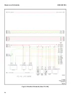
Page 22: ...Figure 1 Electrical Schematic Sheet 13 of 45 Diagrams and Schematics 8000 SRM 1904 16...
Page 23: ...Figure 1 Electrical Schematic Sheet 14 of 45 8000 SRM 1904 Diagrams and Schematics 17...
Page 24: ...Figure 1 Electrical Schematic Sheet 15 of 45 Diagrams and Schematics 8000 SRM 1904 18...
Page 25: ...Figure 1 Electrical Schematic Sheet 16 of 45 8000 SRM 1904 Diagrams and Schematics 19...