1 (12/2014)
Revision:
Part no.:
Technical information for Hyster service
centres
This manual is intended solely for the specialized technicians of
the Hyster service network.
4065749
D435.....
R1.4 R1.6N
R1.6 R1.6HD
R2.0 R2.0HD
R2.5
Page 1: ...Revision Part no Technical information for Hyster service centres This manual is intended solely for the specialized technicians of the Hyster service network 4065749 D435 R1 4 R1 6N R1 6 R1 6HD R2 0 R2 0HD R2 5 ...
Page 2: ...ines for correct maintenance and are designed for use by appropriately trained technicians Incorrect maintenance or non compliance with the instructions contained in this manual could cause damage to property or injury and even death to people We therefore recommend that you read this manual carefully and keep it in a good condition so it is always decipherable and complete This manual does not re...
Page 3: ...ard maintenance Use the sections index with the numbered black bands to go quickly to the desired section SYMBOLS Signals a danger that can cause accidents to people or damage to the machine Signals danger due to high temperatures Signals important notes or information to take into particular consideration Signals disposal recycling of harmful substances under the protection of current legislation...
Page 4: ...ade solvents When working outside the garage move the machine preferably onto the level and block it If working on a slope is inevitable block the machine beforehand and move it onto a level area as soon as pos sible with a certain margin of safety Disconnect the batteries and label all the controls to signal that work is in progress Block the machine and every attachment that has to be raised Nev...
Page 5: ...te has been lost Always use belts ropes or suspension elements of suitable dimensions Concerning the suspension elements take into consideration the lifting angle and any unbalancing of the load The bells on the suspension elements must be sized in proportion to the hook of the overhead travelling crane and anyhow must be free to move easily Always rest the load in the race of the hook Never load ...
Page 6: ...more information Please click here Then get the complete manual NOTE If there is no response to click on the link above please download the PDF document first and then click on it Have any questions please write to me admin servicemanualperfect com ...
Page 7: ...00 8400 4800 blue 240 8000 16000 11200 6400 orange 300 10000 20000 14000 8000 Coefficient 1 2 1 4 0 8 Colour Working load capacity kg purple 1000 2000 1400 800 green 2000 4000 2800 1600 yellow 3000 6000 4200 2400 grey 4000 8000 5600 3200 red 5000 10000 7000 4000 brown 6000 12000 8400 4800 blue 8000 16000 11200 6400 orange 10000 20000 14000 8000 orange 12000 24000 16800 9600 orange 15000 30000 2100...
Page 8: ...ng load capacity kg purple 1000 1400 2100 2100 green 2000 2800 4200 4200 yellow 3000 3800 6300 6300 grey 4000 5600 8400 8400 red 5000 6600 9800 10500 Coefficient 1 1 4 2 1 2 1 Working load capacity the working load capacity is calculated with an angle at the centre of 90 ...
Page 9: ...inal diameter TORQUE SETTING Nm Class 8 Class 10 M3 4 5 2 M4 7 9 15 M5 12 14 14 8 M6 17 2 20 9 M8 31 8 38 1 M10 50 5 60 3 M12 74 2 88 5 M14 101 2 120 8 M16 138 2 164 9 M18 176 6 203 5 M20 225 4 259 7 M22 278 8 321 2 M24 324 8 374 2 M27 422 3 486 5 M30 516 1 594 7 Pre load N TORQUE SETTING Nm Class 5 8 Class 8 8 Class 10 9 M4 0 7 7 3 2400 1 92 1 44 3 07 2 3 4 17 3 13 M5 0 8 8 4 3880 3 88 2 91 6 2 4...
Page 10: ...6 140 90 190 1 5 8 12 20 210 135 285 1 7 8 12 24 290 200 380 2 1 2 12 32 450 300 600 REMOVING FEMALE BSP UNF thread Torque setting Nm Nominal torque max G1 4 20 15 25 G3 8 34 27 41 G1 2 60 42 76 G5 8 69 44 94 G3 4 115 95 135 G1 140 115 165 G1 1 4 210 140 280 G1 1 2 290 215 365 G2 400 300 500 METRIC REVOLVING FEMALE UNF thread Outside diameter of the pipe Torque setting Nm Nominal torque min max M ...
Page 11: ...in the pipe the presence of blisters softening wear of the external coat Pre installation inspection Before installing a flexible hose it is necessary to inspect the pipes carefully First check that the type size reference code and length are correct then check there is no debris blockages bubbles peeling of the outer layer or any other visible defects Installation Avoid twisting the pipe which co...
Page 12: ...5 INTRODUCTION SECTION CONTENTS Installation and settings Diagnostics and measurements Electrical system Truck base mechanics Mast assembly mechanics Small fork mast mechanics Braking system Reduction gear Standard maintenance Hydraulic system Presentation ...
Page 13: ...SERVICE 12 INTRODUCTION ...
Page 14: ...ESENTATION 2 VIEWS OF THE TRUCK 3 TRUCK AND LOAD IDENTIFICATION DATA 4 TRUCK IDENTIFICATION DATA PLATE 4 RESIDUAL LOAD PLATE 4 MAST SERIAL NUMBER PUNCHING and location of documentation 5 GENERAL SPECIFICATIONS 6 BATTERIES TABLE 10 SERVICE ...
Page 15: ...s system Controller Area Network Bus There are two separate CAN Bus lines to improve the efficiency reliability and independence of the modules Hydraulic system The 14 kW pump motor provides excellent performance thanks to the technology with proportional sole noid valves for the carriage out return lifting lowering fork tilting and side shifting operations with smooth movements of the actuators M...
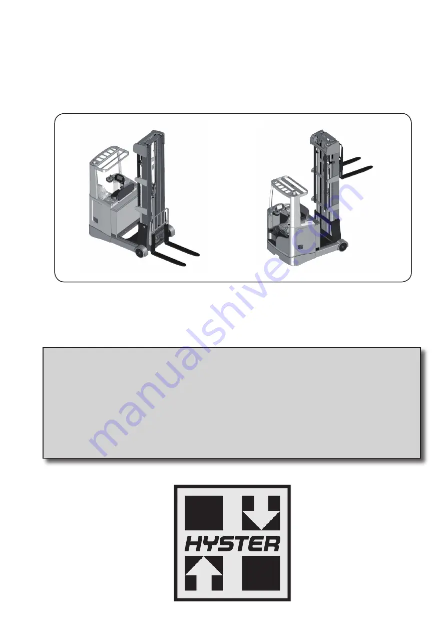
Page 16: ...3 PRESENTATION VIEWS OF THE TRUCK SERVICE ...
Page 17: ... battery weight Min battery weight Battery voltage Nominal load capacity Persons on board RESIDUAL LOAD PLATE The load plate is located on the roof assembly The load plate bears the following data Model Liftable load values up to varying heights up to the maximum load with different distances from the load centre of gravity of the forks Always refer to the load plate to be sure to lift an admissib...
Page 18: ...MAST SERIAL NUMBER PUNCHING and location of documentation The mast serial number is stamped on the mast itself The truck documentation is stored in the docu ment holder behind the backrest of the seat xxxxxxxx SERVICE ...
Page 19: ...6 PRESENTATION GENERAL SPECIFICATIONS SERVICE ...
Page 20: ... b3 mm 700 700 700 4 25 outer fork width min max 8 b5 mm 220 640 260 680 260 680 4 26 distance between the clamps of the load wheels b4 mm 900 900 795 4 28 retractable travel I4 mm 441 491 385 4 31 ground clearance under mast with load m1 mm 75 75 75 4 32 ground clearance at wheelbase centre m2 mm 75 75 75 4 34 1 working aisle for pallet length 1000 x 1200 crosswise Ast mm 2825 2834 2898 4 34 2 wo...
Page 21: ...2A 4 24 fork carriage width b3 mm 700 700 4 25 outer fork width min max 8 b5 mm 260 680 260 680 4 26 distance between the clamps of the load wheels b4 mm 900 900 4 28 retractable travel I4 mm 541 614 4 31 ground clearance under mast with load m1 mm 65 65 4 32 ground clearance at wheelbase centre m2 mm 65 65 4 34 1 working aisle for pallet length 1000 x 1200 crosswise Ast mm 2846 2938 4 34 2 workin...
Page 22: ...2A 2A 4 24 fork carriage width b3 mm 700 700 4 25 outer fork width min max 8 b5 mm 260 680 260 680 4 26 distance between the clamps of the load wheels b4 mm 900 900 4 28 retractable travel I4 mm 491 464 4 31 ground clearance under mast with load m1 mm 65 65 4 32 ground clearance at wheelbase centre m2 mm 65 65 4 34 1 working aisle for pallet length 1000 x 1200 crosswise Ast mm 2834 2903 4 34 2 wor...
Page 23: ... Ast mm 2718 2771 2718 2771 2826 4 34 2 working aisle for pallet length 800 x 1200 length wise Ast mm 2764 2829 2764 2829 2895 4 35 turning radius Wa mm 1671 1671 1671 1671 1671 6 3 battery in compliance with DIN 43531 35 36 A B C no C C C Super C Super C Super 6 4 battery rated voltage capacity at 5 hours V Ah 48 420 48 560 48 465 48 620 48 775 6 5 battery weight 4 kg 750 939 750 950 1165 1 2 man...