Operation
1900 SRM 97
Operation
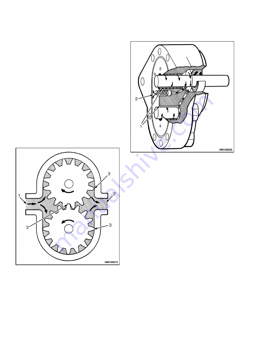
Gear pumps have the teeth of the gears engaged in
the center of the pump. When the input shaft is
turned, the drive gear turns the driven gear. See Fig-
ure 2. The oil in the inlet chamber is moved out from
the center by the teeth of rotating gears. See Fig-
ure 3. The oil between the teeth is moved around
the pumping chamber to the outlet chamber. The oil
is pushed from the outlet chamber by the gear teeth
that are beginning to engage.
The gears and bearings are lubricated by oil from the
outlet side of the pump. A small amount of oil flows
past the gears and into the bearings and to the front
seal cavity. A check ball and spring are installed in
some pumps to keep pressure on the oil in this pas-
sage. The oil pressure prevents air leaks through the
front seal and makes sure there is oil to the bearings.
When the pressure increases to the spring setting,
the ball moves from its seat and oil flows to the inlet
chamber.
1.
INLET
2.
OUTLET
3.
SEAL MADE BY
GEAR TEETH
Figure 2. Gear Pump Operation
1.
OIL ENTERS GROOVES IN BUSHINGS
2.
OIL ENTERS INLET CHAMBER
Figure 3. Check Valve
FLOW CONTROL VALVE
Some of the pumps have a flow control valve in the
rear cover. See Figure 4. The flow control valve has
either a piston and spring, or a cartridge with a pis-
ton and spring. The piston has an orifice that per-
mits a constant volume of oil to flow to the controlled
flow port. When the pump speed increases, the pis-
ton moves to partly open the passage to the main con-
trol valve. This action keeps constant the pressure
difference across the orifice. A constant pressure dif-
ference between both sides of an orifice causes a con-
stant flow through the orifice.
2
Summary of Contents for D174
Page 1: ...Hyster D174 R30XMS2 Forklift...
Page 6: ...THE QUALITY KEEPERS HYSTER APPROVED PARTS...
Page 23: ......


