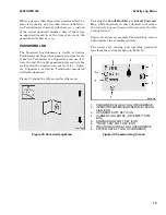
1. PERFORMANCE MODE INDICATOR - IN-
CREASE
2. PERFORMANCE MODE SOFT KEY - IN-
CREASE
3. PERFORMANCE MODE SOFT KEY - DE-
CREASE
4. PERFORMANCE MODE INDICATOR - DE-
CREASE
5. CURRENT PERFORMANCE MODE
Figure 10. Performance Mode Controls
STATUS AND WARNING ICONS
When the truck is powered ON, the system contin-
uously monitors a number of parameters and dis-
plays up to six icons to provide status information
and warnings to the operator, as shown in Fig-
ure 11. Also see the Operating Screen Icons topic.
1. SERVICE DUE
2. MOTOR TEMPERATURE HIGH
3. BRAKE FLUID LOW WARNING
4. SEAT BELT WARNING
5. DIRECTION / PARK BRAKE INDICATORS
6. STEER ANGLE
Figure 11. Status and Warning Icons
NOTE:
Icons for front and rear lights are shown.
These are optional features.
Depending on conditions, the following icons can
appear in this area (see the Operating Screen Icons
topic):
• Wrench Icon
• Temperature High Icon
• Brake Fluid Low Icon
• Hydraulic Fluid Level Icon
• Hydraulic Filter Icon
• Fasten Seat Belt Icon
2200 SRM 1336
Operating Screen
61
Summary of Contents for A1.3-1.5XNT
Page 6: ... THE QUALITY KEEPERS HYSTER APPROVED PARTS ...
Page 9: ...Figure 3 Technician Flowchart Sheet 1 of 4 2200 SRM 1336 Menu Flowchart 3 ...
Page 10: ...Figure 3 Technician Flowchart Sheet 2 of 4 Menu Flowchart 2200 SRM 1336 4 ...
Page 11: ...Figure 3 Technician Flowchart Sheet 3 of 4 2200 SRM 1336 Menu Flowchart 5 ...
Page 12: ...Figure 3 Technician Flowchart Sheet 4 of 4 Menu Flowchart 2200 SRM 1336 6 ...
Page 123: ......
Page 124: ...TECHNICAL PUBLICATIONS 2200 SRM 1336 2 14 8 13 4 13 12 12 3 12 12 11 ...


