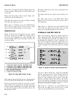
DIRECTION SWITCH
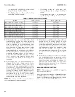
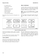
Use this submenu to view the current status of the
direction switch. A solid (filled) up arrow indicates
the currently selected direction is forward as shown
in Figure 74.
Figure 74. Direction Switch Example
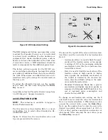
If both directions are indicated on the display, it
means the user has pressed both the forward and
reverse switches on a Monotrol pedal.
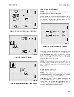
When a Null Icon (circle with diagonal line across
it) appears over the Forklift Truck Icon in the top
right corner of the screen, it means traction and hy-
draulics are deactivated.
TRACTION MOTOR 1 STATUS
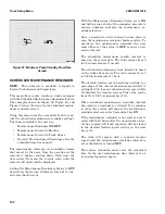
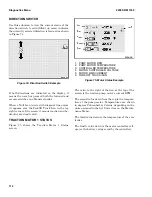
Figure 75 shows the Traction Motor 1 Status
screen.
1. PUMP MOTOR RPM
2. PUMP MOTOR TEMPERATURE
3. CONTROLLER TEMPERATURE
4. MOTOR CONTROLLER VOLTAGE
5. MOTOR RMS CURRENT
6. FORKLIFT TRUCK ICON
Figure 75. Motor Status Example
The value to the right of the icon at the top of the
screen is the traction pump motor's current RPM.
The second value down from the top is the tempera-
ture of the pump motor. Temperatures are shown
in degrees Fahrenheit or Celsius, depending on the
units assigned in the Set Units item on the Mainte-
nance Menu.
The third value down is the temperature of the con-
troller.
The fourth value down is the motor controller volt-
age (or the battery voltage read by the controller).
Diagnostics Menu
2200 SRM 1336
112
Summary of Contents for A1.3-1.5XNT
Page 6: ... THE QUALITY KEEPERS HYSTER APPROVED PARTS ...
Page 9: ...Figure 3 Technician Flowchart Sheet 1 of 4 2200 SRM 1336 Menu Flowchart 3 ...
Page 10: ...Figure 3 Technician Flowchart Sheet 2 of 4 Menu Flowchart 2200 SRM 1336 4 ...
Page 11: ...Figure 3 Technician Flowchart Sheet 3 of 4 2200 SRM 1336 Menu Flowchart 5 ...
Page 12: ...Figure 3 Technician Flowchart Sheet 4 of 4 Menu Flowchart 2200 SRM 1336 6 ...
Page 123: ......
Page 124: ...TECHNICAL PUBLICATIONS 2200 SRM 1336 2 14 8 13 4 13 12 12 3 12 12 11 ...

