Hypro 9303C SERIES Installation, Operation, Repair And Parts Manual Download Page 2

-2-

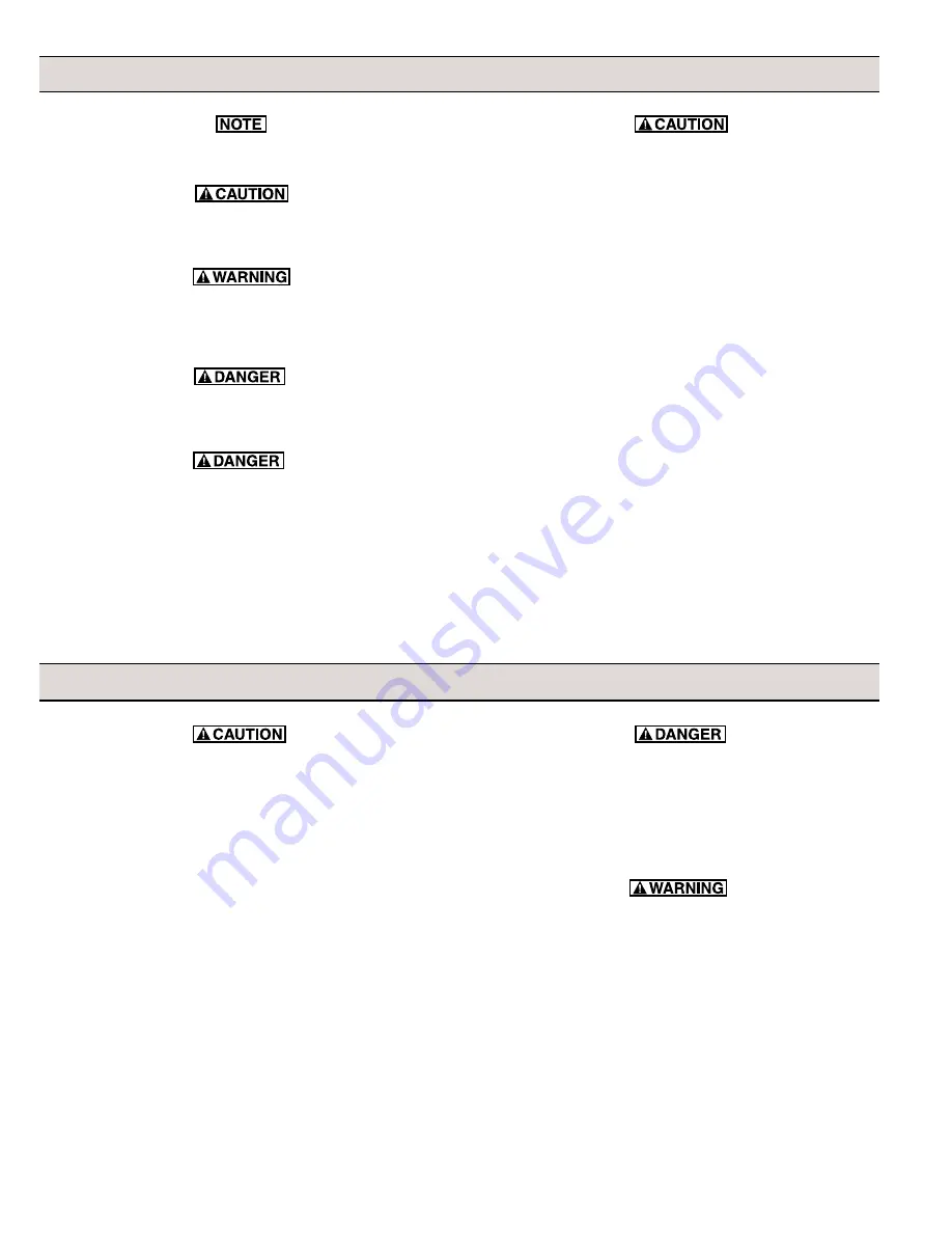
General Safety Information

Notes are used to notify of installation, operation, or maintenance
information that is important but not safety related.

Caution is used to indicate the presence of a hazard, which will
or can cause minor injury or property damage if the notice is
ignored

Warning denotes that a potential hazard exists and indicates
procedures that must be followed exactly to either eliminate or
reduce the hazard, and to avoid serious personal injury, or
prevent future safety problems with the product.

Danger is used to indicate the presence of a hazard
that will result in severe personal injury, death, or property
damage if the notice is ignored.

Do not pump flammable or explosive fluids such as gasoline,
fuel oil, kerosene, etc.  Do not use in explosive atmospheres.
The Pump should be used only with liquids compatible with the
Pump component materials.  Failure to follow this notice can
result in severe personal injury and/or property damage and will
void the product warranty.

1.

Do not pump at pressures higher than the maximum
recommended pressure.

2.

Maximum liquid temperatures is 140

o

 F for Series 9300

centrifugal pumps.

3.

Disconnect power before servicing.

4.

Release all pressure within the system before servicing any
component.

5.

Drain all liquids from the system before servicing any
component. Flush with water.

6.

Secure the outlet lines before starting the pump. An unsecured
line may whip, causing personal injury and/or property
damage.

7.

Check hose for weak or worn condition before each use.
Make certain that all connections are tightly secured.

8.

Periodically inspect the pump and the system components.
Perform routine maintenance as required (See Repair
Instructions).

9.

Use only pipe, hose and fittings rated for the maximum psi
rating of the pump.

10. Do not use these pumps for pumping water or other liquids

for human or animal consumption.

1.

Always drain and flush pump before servicing or
disassembling for any reason.

2.

Always drain and flush pumps prior to returning unit
for repair.

3.

Never store pumps containing hazardous chemicals.

4.

Before returning pump for service/repair, drain out
all liquids and flush unit with neutralizing liquid.
Then, drain the pump.  Attach tag or include written
notice certifying that this has been done.  It is illegal
to ship or transport any hazardous chemicals without
United States Environmental Protection Agency
Licensing.

Hazardous Substance Alert

Never use your hand to check the condition of hydraulic
lines or hoses.  If hydraulic fluid penetrates the skin, get
medical help immediately.  Failure to get proper medical
help may result in loss of limb or life.  The safest way to
check hydraulic lines or hoses is by holding a piece of
cardboard next to the hydraulic line or hose.

The sound pressure level of the Pump is 80dBA.
Observe all safety precautions when operating the Pump
within close proximity for extended periods of time by
wearing hearing protectors.  Extended exposure to
elevated sound levels will result in permanent loss of
hearing acuteness, tinnitus, tiredness, stress, and other
effects such as loss of balance and awareness.

Summary of Contents for 9303C SERIES

Page 1: ...ifugal Pumps SERIES 9303C Cast Iron Centrifugal Pump SERIES 9303P Polypropylene Centrifugal Pump Max Flow Rate 90 gpm Max Pressure 100 psi Ports 1 1 2 NPT Inlet 1 1 4 NPT Outlet Hydraulic Ports 1 2 NP...

Page 2: ...damage 7 Check hose for weak or worn condition before each use Make certain that all connections are tightly secured 8 Periodically inspect the pump and the system components Perform routine maintenan...

Page 3: ...d Sensing flow and pressure compensated Open Center Systems In an Open Center System the hydraulic pump puts out a constant flow If the pump puts out more oil than the motor can use a portion of the o...

Page 4: ...e of air leaks Use good quality hose that cannot be collapsed by suction Relief valves are not normally recommended to regulate spray pressure with centrifugal pumps Strainer Installation Whilelinestr...

Page 5: ...o the motor priority circuit if your tractor has one Standard spool valves which are found on all tractor hydraulic systems can cause potentially damaging high peak pressures in the hydraulic system w...

Page 6: ...pressure drop The flow is adjustable with a flow control valve installed in the hydraulic system Such as the Tortoise Hare control on John Deere tractors Because this system has adjustable flow there...

Page 7: ...ry tap Pump Casing Outlet Port with rubber mallet or hammer to separate Using a 1 2 wrench remove the six bolts from the front For the two bottom bolts securing the Base you will need to hold the two...

Page 8: ...Plastic Seal Nut are fine and can be easily cross threaded To prevent cross threading turn the Plastic Seal Nut counter clockwise until area of thread engagement is detected then turn the Plastic Sea...

Page 9: ...hrust Bearing and two Thrust Bearing Races and the Seal Spacer 2 Remove the Small Retaining Ring next to the Shaft Ball Bearing 3 To remove the Bearing from the Shaft place the Shaft threaded end up i...

Page 10: ...Allen wrench tighten Cap Screws alter nately and evenly in a crisscross pattern to approximately 15 foot pounds 20 Nm of torque 10 Install the Thread Seal Gasket on the Bypass Adjusting Screw PuttheG...

Page 11: ...t port of pump or larger collapsed hose Improperly sized hydraulic motor Refer to Pump Selection Guide to determine proper size hydraulic motor for your hydraulic system Bypass Adjustment Screw not Ad...

Page 12: ...60 40 20 0 0 20 40 60 80 70 50 30 10 100 90 GPM P S I B A R 0 50 100 150 200 250 300 350 9303C HM2C L min 0 3 2 1 4 5 6 5GPM 4GPM 6GPM 100 90 80 70 60 50 40 30 20 10 0 0 20 40 60 80 100 120 140 GPM P...

Page 13: ...0 450 9303P HM5C L min 0 3 2 1 4 5 6 7 8 12 GPM 14 GPM 13 GPM 15 GPM 80 90 70 50 30 10 60 40 20 0 0 20 40 60 80 70 50 30 10 90 GPM P S I B A R 0 50 100 150 200 250 300 9303P HM4C L min 0 3 2 1 4 5 6 5...

Page 14: ...ance Graphs 120 100 140 80 60 40 20 0 0 20 40 60 80 100 120 GPM P S I B A R 0 50 100 150 200 250 300 350 400 450 9303C HM1C SP Performance at 13 GPM L min 0 2 1 3 4 5 6 7 9 8 1 1 2 Inlet Hose Feet of...

Page 15: ...et of Lift 15 10 5 0 1 1 2 Inlet Hose 80 100 120 60 40 20 0 0 20 80 60 100 40 120 GPM P S I B A R 0 50 100 150 200 250 300 350 400 450 9303C HM5C SP Performance at 14 GPM L min 0 3 2 1 4 5 6 7 8 Feet...

Page 16: ...15 10 5 0 2 Inlet Hose 80 60 100 140 120 160 40 20 0 0 20 100 120 140 160 60 80 40 GPM P S I B A R 0 100 200 300 400 500 600 9305C HM3C SP BSP Performance at 19 GPM L min 0 2 4 6 8 10 Feet of Lift 15...

Page 17: ...at GPM at GPM at GPM at Flow 10 PSI 20 PSI 30 PSI 40 PSI 50 PSI 60 PSI 70 PSI 80 PSI 90 PSI 5 GPM 65 56 46 38 20 6 GPM 74 72 64 56 48 38 21 7 GPM 80 75 70 62 57 48 40 28 9 9303P HM2C5 Hydraulic GPM at...

Page 18: ...PM at GPM at GPM at GPM at Flow 10 PSI 20 PSI 30 PSI 40 PSI 50 PSI 60 PSI 70 PSI 80 PSI 90 PSI 100 PSI 110 PSI 13 GPM 90 89 88 85 76 59 40 21 14 GPM 90 89 88 87 85 78 61 43 27 10 15 GPM 90 89 88 87 86...

Page 19: ...Pin HM3C Models 29 1 3900 0022 Gerotor HM1C Models 29 1 3900 0023 Gerotor HM2C Models 29 1 3900 0024 Gerotor HM3C Models 29 1 3900 0025 Gerotor HM4C Models 29 1 3900 0048 Gerotor HM5C Models 30 1 0251...

Page 20: ...29 1 3900 0024 Gerotor HM3C Models 29 1 3900 0025 Gerotor HM4C Models 29 1 3900 0048 Gerotor HM5C Models 30 1 0251 2500C Motor End Plate Includes Main Bearing 31 1 3220 0029 Bypass Adjusting Screw 32...

Page 21: ...ain Bearing 31 1 3220 0029 Valve Stem 32 1 1700 0047 Gasket 33 1 2270 0027 Washer 34 1 2250 0038 Lock Nut 35 4 2270 0039 Washer 36 4 2220 0045 Socket Head Cap Screw HM4C Model 36 4 2220 0044 Socket He...

Page 22: ...0002 Impeller Nut 4 1 0401 9200P Impeller 5 1 2120 0009 Mechanical Seal Viton 6 1 1720 0083 O ring 7 4 2210 0020 Hex Head Cap Screw 8 1 0750 9300C Mounting Flange 11 1 1410 0056 Slinger Ring 12 1 1820...

Page 23: ...Mounting Flange 11 1 1410 0056 Slinger Ring 12 1 1820 0013 Retaining Ring 13 1 1810 0014 Snap Ring 14 1 2000 0010 Ball Bearing 15 1 1410 0073 Spacer 16 1 2104 0005 Shaft Seal 17 1 1410 0074 Seal Space...

Page 24: ...1 1600 0052 Dowel Pin 28 1 1600 0068 Dowel Pin 29 1 3900 0024 Gerotor 30 1 0251 2500C Motor End Plate Includes Main Bearing 31 1 3220 0029 Bypass Adjusting Screw 32 1 1700 0047 Gasket 33 1 2270 0027...

Page 25: ...25 Notes...

Page 26: ...26 Notes...

Page 27: ...27 Notes...

Page 28: ...rves the right to request a Material Safety Data sheet from the Purchaser for any pump or product Hypro deems necessary Hypro reserves the right to disposition as scrap pumps or products returned whic...

Reviews: