SYSTEM CONFIGURATION
940043-002
INTEGRATED ENTERPRISE NETWORK
6-7
IENView Configuration
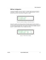
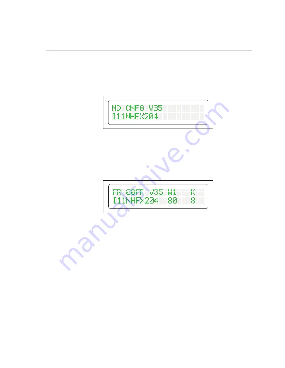
Following the application of power, the IEN 1000 chassis begins a start-up self-test and
configuration indicated by the menu display. Figure 6-6 illustrates the IEN 1000 menu
display during a power-on self-test and configuration process.
Figure 6-6 Power-On Self-test and Configuration Display
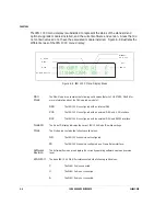
Successful completion of the start-up self-test is indicated by the RUN indicator flashing.
The menu display and status indicators assume appropriate states following the time period
the respective operating system and communication conditions take to establish connection.
Figure 6-7 illustrates the IEN 1000 menu display after start-up.
Figure 6-7 IEN 1000 Menu Display
Summary of Contents for IEN 1000
Page 4: ......
Page 10: ...TABLE OF CONTENTS VI IEN HARDWARE REFERENCE 940043 002 ...
Page 11: ...C H A P T E R 1 Introduction In This Chapter IEN Hardware Reference 1 3 ...
Page 12: ......
Page 14: ...CHAPTER 1 1 4 IEN HARDWARE REFERENCE 940043 002 ...
Page 16: ......
Page 48: ......
Page 108: ...CHAPTER 3 3 62 IEN HARDWARE REFERENCE 940043 002 ...
Page 110: ......
Page 164: ...CHAPTER 4 4 56 IEN HARDWARE REFERENCE 940043 002 ...
Page 166: ......
Page 180: ...CHAPTER 5 5 16 IEN HARDWARE REFERENCE 940043 002 ...
Page 181: ...C H A P T E R 6 System Configuration In This Chapter IEN 1000 Configuration 6 3 ...
Page 182: ......
Page 190: ...CHAPTER 6 6 10 IEN HARDWARE REFERENCE 940043 002 ...
Page 196: ......
Page 197: ......
Page 198: ...Printed in the United States P N 940043 002 Network Systems ...

