background image

19

Operation and maintenance manual, Discfilter HSF2200-1/2F PFC

5.2 Automatic settings

The control system for the HSF2200 series must be equipped with a frequency converter on the 

drive unit. This is factory calibrated if delivered from Hydrotech. The setting on the frequency 

converter must be set for a minimum of 5 seconds “ramp up” and a minimum of 3 seconds “ramp 

down” to give soft start on the drive motor. The filter works with 50 Hz as standard.

If the filter is equipped with a Hydrotech control system, the filter has two operation modes:

1. Continuous rotation (HAND mode)

2. Automatic level control (AUTO mode).

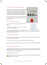
Turn the mode selector to select the operating mode (see E in Figure 5.1).

A

. DRUM DRIVE TRIPPED. LED that indicates 

when the frequency converter has tripped. 

B

. PUMP TRIPPED. LED that indicates when the 

backwash water pump´s motor protection 

device has tripped, 

C

. DRY RUNNING. LED that indicates when the 

dry running protection device for the back-

wash water pump has tripped. 

D

. RESET DRY RUNNING. Resetting the dry run-

ning protection for the backwash water pump. 

E

. OPERATION MODE. Mode selector. 

F

. PUMP. Pump switch. 

G

. CLEANING START. Chemical wash swich, key 

operated. 

H

. CLEANING. LED that indicates when the 

chemical cleaning wash is in progress. 

I

. CLEANING SEQUENCE. Selector for the num-

ber of sequences, chemical cleaning. 

J

. Main power switch.

Figure 5.1 Front of the control cabinet.

Summary of Contents for HSF2200 Series

Page 1: ...Discfilter HSF2200 1 2C PFC Operation and maintenance manual Revised 2019 06 26 ...

Page 2: ...safety 7 2 7 Safety instructions 7 3 HYDROTECH DISCFILTER HSF2200 SERIES 9 3 1 Reception 9 3 2 Storage 9 3 3 Overview 10 3 3 1 HSF2200 type 1 filter with tank 10 3 3 2 HSF2200 type 2 filter without tank 11 3 4 Identifying the filter 13 3 4 1 Definition of filter type 13 4 GENERAL INSTALLATION INSTRUCTIONS 14 4 1 Lifting the equipment 14 4 2 Installation site 16 I 1 1 Outdoor installation 16 I 1 2 ...

Page 3: ...tinuous rotation backwash 21 5 2 3 Operating mode AUTO Automatic level control 21 5 2 4 Adjusting the level sensor 21 5 2 5 Setting of level relay 22 5 3 Backwash system 22 6 FUNCTION 23 6 1 Intended use 23 6 2 Non intended use 23 6 3 Filtration and backwash process 23 7 MAINTENANCE SERVICE 24 7 1 Backwash system 24 7 1 1 Servicing nozzles 24 7 1 2 Self cleaning nozzle 25 7 2 Bearings 26 7 2 1 Lub...

Page 4: ...ing filter panels 31 7 4 Drive chain 33 7 4 1 Checking the drive chain 33 7 4 2 Adjusting drive chain tension 34 7 4 3 Replacing the drive chain 34 7 5 Drive unit 34 7 6 Inlet gasket 35 7 6 1 Checking the inlet gasket 35 7 6 2 Replacing the inlet gasket 35 8 MAINTENANCE SCHEDULE 36 Symbols used on Hydrotech filters 37 Manuals technical information 38 ...

Page 5: ...his manual If this information is ignored it may result in serious personal injury and or damage to equipment The manual must always be available to personnel working with the equipment It is important that The manual and other applicable documents must be kept for the entire duration of the nequipment s lifespan The manual and other relevant documents are included as part of the equipment All rel...

Page 6: ...ised personnel Adequate lighting should be used when operating the filter and when working in close prox imity to the filter 2 1 Warning symbols Warning symbols are used in this manual to draw attention to potentially dangerous situations Information that warns you of a potential risk of personal injury and or damage to equipment Warning stickers see Figure 2 1 are affixed to the filter to warn pe...

Page 7: ...rum from unintentionally starting to rotate when the power is reconnected 2 6 Electrical safety Electrical installation must be carried out by a qualified electrician and in accordance with local regulations Also see Appendix D The filter tank or the frame must be connected to ground Also see section 4 4 The main power switch emergency stop must be fitted in accordance with applicable regula tions...

Page 8: ...ut warning if automatic control is activated Moving parts must not be touched Safety guards are fitted around the power transmission Make sure these are secured and cor rectly fitted The aerosols from the backwash water may contain harmful substances Measured noise levels from the filter are less than 74 dB A Personnel should use appropriate protection when necessary in accordance with local regul...

Page 9: ...ing the equipment see section 4 1 3 2 Storage Some precautions must be taken to prevent damage to equipment if a long storage time is ne cessary several weeks or more The equipment should preferably be stored indoors in a frost free area The filter must be protected against direct sunlight if stored outdoors Heat and UV radiation can damage the filter panels If the filters are delivered inside pla...

Page 10: ...where several filter parts are shown Figure 3 1 Hydrotech Discfilter in HSF2200 series type 1F side view A Connection side B Filter cover C Drive side Figure 3 2 Hydrotech Discfilter in HSF2200 series type 1C inlet side A Connection chemical cleaning B Backwash ramp lever C Lubrication point D Sludge outlet E Inlet F Outlet G Outlet separate emergency overflow bypass optional ...

Page 11: ...dry running protection for pump optional E Manometer F Lubrication points G Drive unit H Insulation valve for pump I Drain tank Figure 3 3 Hydrotech Discfilter in HSF2200 series type 1C drive side A Inlet side B Inlet passage C Filter cover D Drive side 3 3 2 HSF2200 type 2 filter without tank Figure 3 4 Hydrotech Discfilter in HSF2200 series type 2C side view ...

Page 12: ...ge outlet E Inlet F Filter panel G Sludge trough Figure 3 5 Hydrotech Discfilter in HSF2200 series type 2C inlet side Figure 3 6 Hydrotech Discfilter in HSF2200 series type 2C drive side A Manometer B Pressure switch dry running protection for pump optional C Backwash pump optional D Drive unit E Lubrication point F Drive chain G Drum bearings H Filter drum ...

Page 13: ...ying the filter Filter type serial number and year of manufacture are stated on the marking plate The filter type and serial number are also stated on the front of this manual Figure 3 7 Filter marking plate 3 4 1 Definition of filter type Figure 3 8 Definition of filter type ...

Page 14: ...e used when lifting filters in wooden crates Filters with a tank can be lifted using a crane or overhead crane by using the filter s lifting lugs or with a forklift truck WARNING The work area must be fenced off before unloading in accordance with local regulations to prevent unauthorised access Figur 4 1 Lyft av Hydrotech Discfilter i HSF2200 serien typ 1 med tank ...

Page 15: ...2F PFC Filters without a tank can be lifted using a crane or overhead crane by using the filter s lifting lugs Figure 4 2 Shows how lifting devices are attached filter without tank Figure 4 3 Lifting Hydrotech Discfilter in HSF2200 series type 2 without tank ...

Page 16: ...igure 4 4 600 mm wide aisles should be laid out around the filter to permit easy access to the filter during service work The gap between the filter and the concre te structure must be sealed for safety reasons and to keep out foreign objects that can cause blockages in the backwash system 4 3 Electrical connection Qualified electricians must perform all electrical work Electrical connection must ...

Page 17: ...ter HSF2200 1 2F PFC 4 5 Checking drum rotation Start drum rotation and check that the drum rotates in the same direction as the rotation arrow on the drive unit cover 4 6 Pipe connections Piping for reject should have a minimum inclination of 1 ...

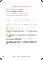
Page 18: ...or to remove a filter panel and fill the filter tank chamber with unfilte red water WARNING A difference in water level between the inside and outside of the filter drum greater than 550 mm will damage the filter 6 When the water level inside the filter tank chamber reaches the pump suction pipe or the pump if a CRK or MTR pump is installed the pump switch must be set to 1 ON position NB Also read...

Page 19: ...vel control AUTO mode Turn the mode selector to select the operating mode see E in Figure 5 1 A DRUM DRIVE TRIPPED LED that indicates when the frequency converter has tripped B PUMP TRIPPED LED that indicates when the backwash water pump s motor protection device has tripped C DRY RUNNING LED that indicates when the dry running protection device for the back wash water pump has tripped D RESET DRY...

Page 20: ...r protection switch pump B Motor protection switch drive unit C Fuse D Fuse E Transformer F Contactor G Relays H Logic module I Level relay J Soft start K Frequency converter L Terminal block M Main power switch Figure 5 2 Component parts of the Hydrotech control cabinet ...

Page 21: ...ration with continuous drum rotation and backwash In this mode the water level inside the drum is kept virtually constant The level sensor and the automatic level control are disabled when HAND operating mode has been selected 5 2 3 Operating mode AUTO Automatic level control With level control enabled drum rotation and the backwash pump are activated when the water level inside the drum reaches t...

Page 22: ...t to the side marked EMPTY on this side there are three different sensi tivity ranges H S and L If appropriate sensitivity cannot be set using the selected sensitivity range another sensitivity range can be chosen 5 3 Backwash system NB Prior to a service read section 2 7 The system pressure for backwashing must be set to 7 9 bar Newly connected pipe systems for external wash water should be flush...

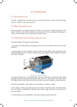
Page 23: ...ents 2 Solid particles are separated from the water with the help of filter media attached to both sides of the filter segments while the clean water passes through the filter media to the outside of the filter segments 3 Operating mode AUTO The solid particles that accumulate on the inside of the filter media gradually reduce the water flow through the filter panel The water level on the inside o...

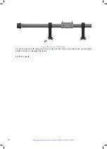
Page 24: ...ntenance The nozzles are accessible when the backwash pipe is extended see below 7 1 1 Servicing nozzles 1 Turn the operating mode switch to 0 OFF 2 Open the cover on the side where the backwash pipe is located 3 Fold out the backwash ramp with the loose lever see Figure 7 1 4 Once servicing is completed place the backwash ramp in its original position with the help of the lever 5 Close and lock t...

Page 25: ...e manual Discfilter HSF2200 1 2F PFC 7 1 2 Self cleaning nozzle Figure 7 2 below shows a self cleaning nozzle A Stop screw B Nozzle attachment C O ring D O ring E Nozzle tip F Nozzle nut Figur 7 2 Dysdetaljer självrengörande dysa ...

Page 26: ...e 7 3 7 2 1 Lubrication of swivel The swivel makes up the bearing between the backwash pipe and the connecting pipe for the backwash water see Figure 7 4 The swivel s lubrication points are shown in Figure 3 3 and Figure 3 5 Check the old grease that comes out during lubrication if it contains traces of water e g whi te grey discolouration the swivel must be replaced Figure 7 3 Figur 7 4 Swivel ...

Page 27: ... The drum must be rotating when the bearings are lubricated Check the old grease that comes out during lubrication if it contains traces of water e g whi te grey discolouration the seals must be replaced and the bearings must be inspected replaced Lubricate the drum bearings according to the recommendations in chapter 8 The lubrication points are shown in Figure 3 2Figure 3 3Figure 3 5 andFigure 3...

Page 28: ...taching a screw nut to the rear drum lifter The cover must be detached before the rear drum lifter can be mounted Position a wooden wedge between the drum and the frame beam prior to lifting with the rear drum lifter to prevent the drum from moving towards the filter s inlet end and to pre vent drum lifter play The drum lifters are shown below A Hydraulic jack B Bracket C Mouting screws Figure 7 6...

Page 29: ...uipment The cleaning products must not be mixed If for example HCl and NaClO are mixed this produces toxic chlorine gas HCl and NaOH are highly corrosive For safety advice see app licable local regulations For more detailed instructions please contact your supplier Hydrotech Discfilters in the HSF2200 series as standard are prepared with a chemical ramp to make removal of long term clogging of the...

Page 30: ...nce manual Discfilter HSF2200 1 2F PFC 2 Clean the nozzle with compressed air or a plastic brush Never use a wire brush metal rods or similar as these can damage the nozzle 3 Refit the nozzle Figure 7 9 Nozzles on chemical ramp ...

Page 31: ...gure 7 10 1 Turn the main power switch to the OFF 0 position and lock with a padlock 2 Undo the filter segment cover screws and remove the cover see Figure 7 11 3 Pull out the filter panel see Figure 7 12 4 Insert a new filter panel and slide it in until it bottoms NB Filter panels with steel frames must be positioned with the filter cloth facing inwards see Figure 7 13 Incorrect installation of t...

Page 32: ...l Discfilter HSF2200 1 2F PFC 5 Replace the filter segment cover and tighten the screws Maximum tightening torque of 3 Nm 6 Fit the remaining filter panels and covers in the same manner 7 Start operations again as set out in section 5 1 ...

Page 33: ...to the OFF 0 position and lock with a padlock 2 To access the chain detach the motor cover and if necessary the chain tray 3 Stretch the chain by turning the drum by hand in either direction 4 On the chain s non tensioned section use a steel rule to check that measurement A is 5 15 mm see Figure 7 14 5 Adjust the chain setting if necessary according to section 7 4 2 6 Start operations again as des...

Page 34: ... operation as described in section 5 1 When the drive chain cannot be adjusted any further the chain is worn out and must be re placed see section 7 4 3 7 4 3 Replacing the drive chain 1 Turn the main power switch to the OFF position and lock with a padlock 2 Adjust the drive unit to its end position see section 7 4 2 3 Remove the chain lock and chain 4 Fit the new drive chain 5 Adjust drive chain...

Page 35: ...or damage and wear see Figure 7 17 5 If necessary replace the inlet gasket in accor dance with section 7 6 2 6 Start operations again as set out in section 5 1 7 6 2 Replacing the inlet gasket 1 Turn the main power switch to the OFF 0 position and lock with a padlock 2 Reduce the water level in the filter until the whole inlet gasket is accessible 3 Note how the inlet gasket is fitted before it is...

Page 36: ...lication in question Lubricate the swivel to the backwash pipe using grease of the type NLGI 2 e g Molykote Multilub Rembrandt EP or equivalent grease See section 7 2 1 Twice a month with continuous drum rotation Once a month with intermittent drum operation Lubricate the drum bearings on the inlet and drive side using grease of the type NLGI 2 e g Molykote Multilub Rembrandt EP or equivalent grea...

Page 37: ...nformation about lubrication Symbol displaying moving parts Neg ligence to comply with safety regula tions may lead to injury This symbol is placed where certain attention is needed when handling the filter Read the manual for further information Warning for high voltage Always as sume all electrical equipment to be live and Used as a warning where corrosive fluids is used Always use appropriate s...

Page 38: ...chnomaps veoliawatertechnologies com hydrotech en Click on Manuals technical information in the list on the left side Select the product you want more information about and it will open a Pdf in a new tab You can also find information regarding products used on Hydrotech filters e g motors pumps actua tors etc Hydrotech microscreen filters webpage ...

Page 39: ...ilter HSF2200 1 2F PFC Hydrotech AB A Veolia Solutions Technologies Company Mejselgatan 6 235 32 Vellinge Sverige Telefon 46 0 40 42 95 30 Fax 46 0 40 42 95 31 E mail mailbox hydrotech se Hemsida www hydrotech se Copyright All rights reserved ...

Reviews: