


3
a pH ranging from 5 to 9, specific
gravities from 0.9 to 1.1, viscosities
ranging from 28 to 35 S.S.U., and
temperatures up to 140°F.
Receiving Pump:
Inspect pumps on arrival for
possible concealed damage in
shipping. Any damage should
be reported immediately to
delivering carrier. Claims for
damage must originate at the
receiving end. Claims for shipping
damage cannot be processed at
the factory.
Codes:
All local wiring codes must be
observed. Consult the local
inspector before installation to
avoid costly delays that can
occur due to rejection after job
is finished.
Pump Not Operating or in
Storage:
Pumps with carbon ceramic
seals must have manually
rotated (6 revolutions) after
setting non-operational for 3
months or longer and prior to
electrical start-up.
Installing Pump in Sump:
Before installing pump in sump,
lay it on its side and rotate grinder
shaft. Stator boot and rotor
may be slightly stuck due to
factory test water, so it must be
broken loose by rotating shaft
with a screwdriver at grinder end.
The common shaft should turn
with a slight resistance. Slight
lubrication by means of a small
amount of lubricating oil down
the cavity inlet of the stator boot
and rotating shaft to pre-lube
stator boot and rotor before start is
recommended. Do not connect the
power until after this test.
Clean all trash and sticks from
sump and connect pump to piping.
A check valve must be installed
on each pump.
Location:
If pumps are installed in an
existing basin or concrete sump,
the piping can either be connected
permanently or rails and brackets
can be furnished for mounting to
walls of basin. In either case, be
sure that the Hydromatic non-clog
check valve is used and that
the pumps are submerged in a
vertical position. The complete
factory built packaged system is
recommended for the most
satisfactory installation and
generally for the lowest cost
where expensive installation labor
is involved.
Making Electrical Connections:
All electrical wiring must be in
accordance with local code, and
only qualified electricians should
make the installations. Complete
wiring diagrams are included for
use in making the installation. All
wires should be checked for shorts
to ground with an ohmmeter or
Megger after the connections
are made. This is important, as
one grounded wire can cause
considerable trouble.
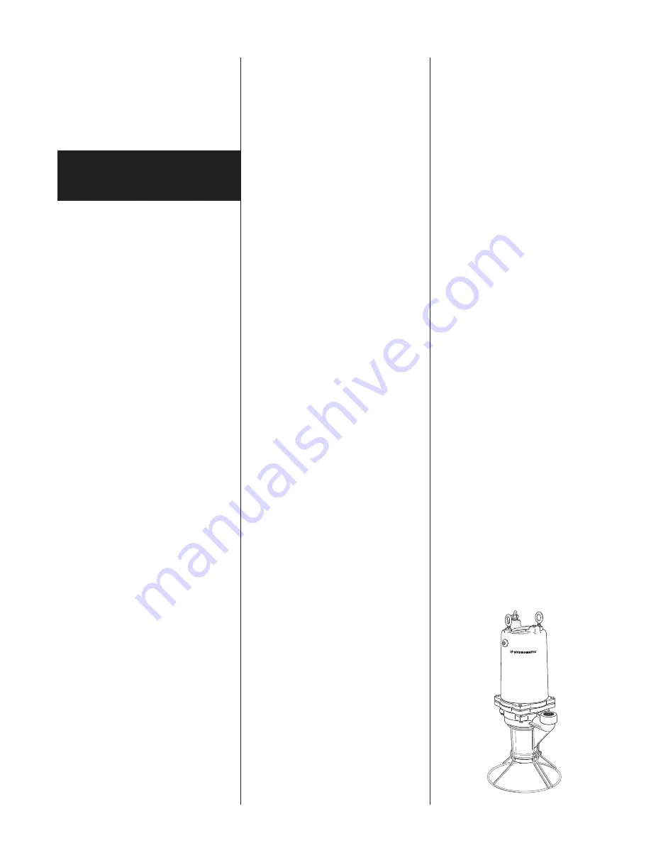
Pump Description:
The Hydromatic pumps covered
by these instructions are
submersible grinder pumps.
The cutter blades are on the suction
side of the positive displacement
pump impeller and discharge
directly into the inlet of the
impeller. The integral stainless
steel pump motor shaft is sealed
by a single mechanical seal.
Two ball bearings are used to
handle the loads in this design.
The upper bearing takes radial
loads, while the larger lower
bearing handles both thrust and
radial loads. Both bearings are
permanently lubricated by the
dielectric oil in the motor housing.
The motor is fixed within the
motor housing and is completely
submerged in the dielectric oil for
maximum heat transfer. The motor
housing and seal chamber are
completely sealed with O-rings
located at mating part faces. The
power cord entry system is
designed to give reliable sealing.
The first seal is made by
compression of a rubber gasket by
the cord grip, thereby expanding
to fill the cord entry of the motor
housing. The cord grip forms a
second seal around the molded
cord end and provides strain relief.
Application:
These pumps are designed for
either residential or industrial
sewage discharge applications with
11.
CAUTION
– Never work on
pump with power on. Make
sure that the ground wire is
securely connected and that the
unit is properly grounded in
accordance with local codes.
Pump
Installation
Summary of Contents for HPD200
Page 11: ......


