


4
CHANGES AND T YPING ERRORS RESERVED
CHANGES AND T YPING ERRORS RESERVED
2. a
ddiTional
safeTy
rules
Always keep in mind that:
• the machine must be switched off and disconnected from the power supply during maintenance and repairs,
• clamped workpieces may only be measured when the machine is switched off.
Never lean over the machine, mind loose clothing, ties, jewellery etc. and wear a cap.
Do not remove safety devices or guards. Never use the machine while a guard is open.
Always use safety glasses for machining rough materials.
Burrs and chips should only be removed using a sweeper or other aid, never with your bare hands!
Never leave the machine running unattended.
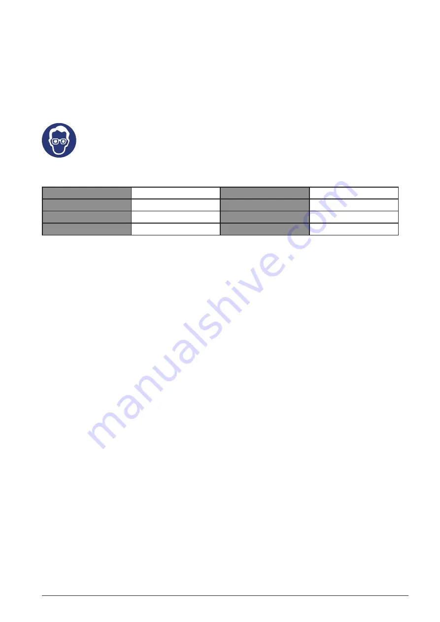
Always wear safety glasses!
3. s
pecificaTion
Tank capacity
50 l
Speed
2850 min-1
Motor power
1.5 kW
Voltage
230 V
Max. consumption
198 ltr/min
Weight
35 kg
Max. pressure
8 bar
Dimensions (w x h)
785 x 325 x 665 mm
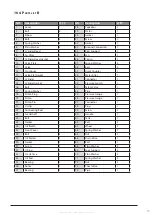
4. m
achine
parTs
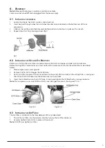
Air Regulator:
The Air Regulator controls the air flow pressure. Tum regulator clockwise to increase air pressure,
counter-clockwise to decrease.
Handle:
Convenient, rubber gripped handle allows for easy transport of your Air compressor.
Air Outlet:
Using Air Quick Coupler allows for fast easy connection to an air hose. Otherwise Air Cock turn
clockwise to stop air, turn counter-clockwise to release air.
Tank Drain Valve:
The Tank Drain Valve can be opened to allow moisture and compressed air to be released from
the air Tank.
Warning: Tank Drain Valve should always be opened slowly to avoid damage to equipment and possible
injury.
Air Filter:
This Air filter keeps your compressor running cleanly, by filtering out impurities.
Oil Breather:
As the compressor motor operates pressurized air must be released from the crank case. The Oil
Breather allows built up air to escape, while shielding you Air Compressor from airborne impurities.
Pressure Switch:
The red knob Pressure Switch turns the Air Compressor on and off. When Switch -is pulled-up
position, compressor is turned ON. When switch is in pushed - down position, compressor is turned OFF.
Note
: Always make sure that compressor Pressure Switch is in the OFF position before performing and
maintenance or plugging the compressor into a power supply.
Safety Valve:
The Safety Valve device relieves pressure from the Air Tank in the event of excessive pressure build
up. The Safety Valve is preset at factory. Do not attempt to make any adjustments to the Safety Valve. Periodically
pull ring on the Safety Valve end to check that it is working properly.
Air Tank:
Powder coated steel tank, stores the compressed air until it is needed.
1. ing it clockwise.
2. The spindle return spring adjustment is complete.
5. G
eTTinG
sTarTed
Before operating your tool, check the contents of the box to make sure you have everything you need.
Items included in the box:
• Air Compreessor
• Air Filter
• Oil Breather
• Wheels(2)
• Mounting Hardware for Wheels
• Owner’s Manual


