background image

Rev. 0608 

1

DA

TE

:

PROJEC

TI

TL

E:

DR

AW

ING #:

DRA

W

N

 BY

:

PRODUC

TION ORDER #:

DRA

W

ING 

TI

TL

E:

DA

TE

:

H

us

sm

an

C

orporation, Int'l.

13770 Ramona Avenu

e

C

hi

no

, C

A

. 9

17

10

(909

)-590-4910     Lic.#: 644406

REVIS

IO

NS

:

#:    DE

SCRIPT

ION:

C

H

E

C

K

E

D

 B

Y

:

BY:

FILE LOCA

TI

ON:

JE

S

S

E

 R

IO

S

PAGE     OF

?

1

2

5/

14

/0

7

W

18

00

16

7

R3

-P

-8

-R

EM

91

42

76

L

CO

N

TAC

TO

R

SQUARE -D 89

10

D

P

A

43

V

02

12

5-

01

-1

00

1

L

~2

08

 / 

~2

40

 V

A

C

 - 

50

/6

H

Z

P

A

C

K

TR

O

N

IC

S

CO

N

TROLLER

22

5-

01

-3

22

9

L

TE

M

P

. C

O

N

TR

O

L

SENSOR

225

-01

-32

28

6

4

2
1

5

P1

3

7

G

R

ID

D

LE

 H

E

A

TER - 

TH

ERMO

FL

E

X™

(2) 34

W

, 1

.4

3A

 @

 2

40

 V

A

C

22

5-

01

-6

78

7T

BA

LLA

ST 

125

-01

-32

66

FU

LH

AM

 LH

3-1

20-

L

S

W

IT

CH

TI

P

P

E

TT

E

12

5-

01

-0

31

1

L1 L2

N G

P

IL

O

LI

G

H

T

17

5-

01

-1

10

2C

RJ-45 NETW

O

R

K

 J

A

C

K

12

5-

01

-0

20

2

D

U

P

LE

X

12

5-

01

-3

17

8

CIR

C

U

IT

 # 

3

W


G


B

K

LI

G

H

T CIRCU

IT

= .47A

CIRC

UI

#2

BL

K # 14

R

E

D

 #

 1

4

WH

T #

 14

BLA

CK 

#14

F28

T5-

48"

125

-03

-11

31

G

R

N

 #

 1

4

SENSOR

225

-01

-32

28

F28

T5-

48"

125

-03

-11

31

FAN MO

TO

R

0.

29

 A

M

P

 @

 1

20

V

A

C

(4

) 0

39

24

57

M

M

M

M

SENSOR COM

TROL

90

TB

00

2G

01

22

5-

01

-2

02

8

BUND

LE

BR

O

W

N

LABELE

D

FAN 

C

IRCUI

T

T-

S

TA

T

(1) 225-01-071

0

S

U

C

TI

O

N

 S

O

LE

N

O

ID

(1) 

22

5-01-3

206

BU

N

D

LE

W

H

IT

E/

BL

AC

K

LA

B

E

LE

D

TH

ERMO

ST

AT

CIRC

UI

T

~120 VAC - 

60

 H

z

L1


 N

MCA= 

.59A

M

O

P

= 15A

BLA

CK

 #1

4

WH

ITE

 #1

4

~120 VAC - 1Ø - 60

 H

z

~120 VAC - 

60

 H

z

M

C

A

1.23A

M

O

P

15

A

BU

N

D

LE

YE

LL

O

W

LA

B

E

LE

D

RECEP

TA

C

LE

CIRC

UIT

BU

N

D

LE

ORANGE LA

B

E

LE

D

LI

GH

CIRCUI

T

MCA= 

3.5

8A

MOP=

 15

A

L1


  N

L1


 N

BLA

CK

 #1

4

WH

ITE

 #1

4

BLACK #14

WH

ITE

 #1

4

W

A

RM

ER

12

5-

01

-0

76

7

TY

C

O

THERM

AL

CON

TROLS

10

B

TV

1-

C

R

80

 W

AT

TS

0.

67

A

M

P

@

12

0V

BUND

LE

PURP

LE

LABELE

D

HEAT

ER

CIRC

UI

T

LI


 N

~1

20

 V

A

C

 - 

 - 

50

/6

H

z.

MCA= 

.84A

MOP=

 15

A

BOHN CO

IL

 A

S

S

Y

(1

) V

A

-0

12

0V

 0

.8

A

22

5-

02

-0

51

3

M

C

A

2.0A

M

O

P

15

A

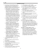
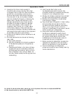
wiring diagrams (cont'd)

Summary of Contents for Specialty Products R3P

Page 1: ...Refrigerated Service and or Prep with refrigerated self service front P N IGFP R3 R3P 0608 INSTALLATION OPERATION GUIDE CHINO R3 R3P Ref Service self service prep case Rev 0608 Installation Operation...

Page 2: ...ains Information on R3 Refrigerated Service Top Self Service Front Case R3P Service Prep Top Refrigerated Self Service Front Case R3TO Service Top only for in counter installation Shipping Damage All...

Page 3: ...tional Shelf R3P Service Prep Self Service Case Scale 1 2 12 3 8 18 10 20 5 8 13 1 2 50 3 8 19 3 8 6 36 3 8 13 1 2 50 3 8 50 1 4 40 1 2 52 1 8 20 5 8 2 0 7 8 10 5 8 Prep Top Area 19 3 8 12 6 12 8 R3 O...

Page 4: ...fect of one continuous display A joint trim kit is supplied with each joint Leveling IMPORTANT IT IS IMPERATIVE THAT CASES BE LEVELED FROM FRONT TO BACK AND SIDE TO SIDE PRIOR TO JOINING A LEVEL CASE...

Page 5: ...ten Join the top by using a joint bracket included in joint kit with 3 8 bolts Joint Trim After cases have been leveled and joined and refrigeration electrical and wasted piping work completed install...

Page 6: ...easure 10 inches from top of the case Note Line up 6 inch mark with 10 inch mark Step 3 Use bracket center hole to align with cross mark Note Use pencil marker to mark hole pattern HOLE PATTERN Step 4...

Page 7: ...ont d Step 6 Install upper support bracket Step 7 Mount wrap board on top of bracket using a spacer to have a gap between rear wall and board Step 8 screw bracket into wrap board screws provided 8 X 1...

Page 8: ...bumper slide into the channel Step 3 Starting on one end while inserting the bumper push it up against the end cap to prevent the bumper from shrinking after installation when it gets cold Step 4 As y...

Page 9: ...ositioned within the base grooves Roll vinyl top over full length of base then tap with rubber mallet to ensure vinyl is securely locked into the base 2b Rigid Top Snap the Rigid Top over the Rigid Ba...

Page 10: ...length of base then tap with rubber mallet to ensure vinyl is securely locked into the base 2b Rigid Top Snap the Rigid Top over the Rigid Base 3 If necessary wipe clean with any household cleaning pr...

Page 11: ...gs are positioned within the base grooves Roll vinyl top over full length of base then tap with rubber mallet to ensure vinyl is securely locked into the base 2b Rigid Top Snap the Rigid Top over the...

Page 12: ...ins are located in dead air spaces between refrigerators or between a refrigerator and a wall provide means to prevent freezing The water seal should be insulated to prevent condensation Refrigerant T...

Page 13: ...E Refer to label affixed to case to determine the actual configuration as checked in the TYPE INSTALLED boxes Electrical Circuit Identification Standard lighting for all refrigerated models will be fu...

Page 14: ...pidly deteriorate 3 Maintain the display merchandisers temperature controls as outlined in the refrigerator section of this manual 4 Do not place any product into these refrigerators until all control...

Page 15: ...nti fog capabilities This product also seals pores and provides a protective coating User Information Cont d CLEANING PRECAUTIONS When cleaning Do not use high pressure water hoses Do not introduce wa...

Page 16: ...rams R3 Prep 4 W0180047 6 W0180048 8 W0180049 12 W0180051 R3 P 8 REM 8 W1800167 R3 P 4 REM WALMART 4 W1800172 R3 P 6 REM WALMART 6 W1800173 R3 Top Only Cold 4 W0180101 6 W0180102 8 W0180103 12 W018010...

Page 17: ...load ratings removed fuse 8 29 07 JR 03 17 06 R3 CR3 CASES W0180047 R3 CR3 4 PREP CASES LIGHT SWITCH TIPPETTE 125 01 0311 L F28T5 48 125 03 1131 LIGHT CIRCUIT TAG ORANGE FAN CIRCUIT TAG BROWN BALLAST...

Page 18: ...IGHT SWITCH TIPPETTE 125 01 0311 L LIGHT CIRCUIT TAG ORANGE FAN MOTOR CIRCUIT TAG BROWN BALLAST 125 01 3266 FULHAM LH3 120 L FP21 830 T5 36 125 03 1131 FP21 830 T5 36 125 03 1131 EVAP FAN MOTORS 4 4W...

Page 19: ...LIGHT SWITCH TIPPETTE 125 01 0311 BALLAST 125 01 3266 FULHAM LH3 120 L L F28T5 48 125 03 1131 F28T5 48 125 03 1131 LIGHT CIRCUIT TAG ORANGE FAN CIRCUIT TAG BOTTOM BROWN M M M M EVAP FAN MOTORS 4 4W 29...

Page 20: ...CASES LIGHT SWITCH TIPPETTE 125 01 0311 BALLAST 125 01 3266 FULHAM LH3 120 L L F28T5 48 125 03 1131 F28T5 48 125 03 1131 LIGHT CIRCUIT TAG ORANGE FAN MOTOR TAG BROWN M M M M M M EVAP FAN MOTORS 6 4W...

Page 21: ...3178 CIRCUIT 3 W G BK LIGHT CIRCUIT 47A CIRCUIT 2 BLK 14 RED 14 WHT 14 BLACK 14 F28T5 48 125 03 1131 GRN 14 SENSOR 225 01 3228 F28T5 48 125 03 1131 FAN MOTOR 0 29 AMP 120VAC 4 0392457 M M M M SENSOR...

Page 22: ...90 4910 Lic 644406 REVISIONS DESCRIPTION CHECKED BY BY FILE LOCATION JESSE RIOS PAGE OF 2 2 4 12 07 W1800167 R3 P 8REM 914276 LOADING 120 V L1 L2 L3 3 9 NOTE CASE MUST BE GROUNDED LOADING 208 V 240V L...

Page 23: ...65A MOP 15A BUNDLE ORANGE LABELED LIGHT CIRCUIT L1 N L1 N BLACK 14 WHITE 14 BLACK 14 WHITE 14 WARMER 4ft 125 01 0767 TYCO THERMAL CONTROLS 10BTV1 CR 40 WATTS 0 33AMP 120V BUNDLE PURPLE LABELED HEATER...

Page 24: ...N BLACK 14 WHITE 14 BLACK 14 WHITE 14 WARMER 6ft 125 01 0767 TYCO THERMAL CONTROLS 10BTV1 CR 60 WATTS 0 5AMP 120V BUNDLE PURPLE LABELED HEATER CIRCUIT LI N 120 VAC 1 50 60 Hz MCA 63A MOP 15A BOHN COIL...

Page 25: ...1 0311 L F28T5 48 125 03 1131 T STAT 1 225 01 0707 SUCTION SOLENOID 1 225 01 3202 BUNDLE BLACK WHITE BUNDLE BROWN AXIAL EVAP FANS 0 16 AMP 11W 120VAC 2 125 01 2011 BALLAST 125 01 3266 FULHAM LH3 120 L...

Page 26: ...0311 L T STAT 1 225 01 0707 SUCTION SOLENOID 1 225 01 3202 BUNDLE ORANGE BUNDLE WHITE BLACK M BUNDLE BROWN BALLAST 125 01 3266 FULHAM LH3 120 L FP21 830 T5 36 2 125 03 1131 120 VAC 60 Hz MCA 49A MOP 1...

Page 27: ...11 BALLAST 125 01 3266 FULHAM LH3 120 L L F28T5 48 2 125 03 1131 T STAT 1 225 01 0707 SUCTION SOLENOID 1 225 01 3202 BUNDLE ORANGE BUNDLE WHITE BLACK BUNDLE BROWN M M M M 120 VAC 60 Hz MCA 65A MOP 15A...

Page 28: ...AST 125 01 3266 FULHAM LH3 120 L L F28T5 48 125 03 1131 F28T5 48 125 03 1131 T STAT 1 225 01 0707 SUCTION SOLENOID 1 225 01 3202 BUNDLE ORANGE BUNDLE WHITE BLACK BUNDLE BROWN M M M M M M 120 VAC 60 Hz...

Page 29: ...GON 8045 00 115 V 60 Hz 125 01 0710 CONDENSER FAN T STAT POWER SWITCH M M M BUNDLE YELLOW SAFETY SWITCH FLOAT SWITCH 120 VAC 60 Hz MCA 15 6A MOP 20A PLUG NEMA 5 15P L1 N BLACK 14 WHITE 14 FISHER EVAPO...

Page 30: ...orm a complete start up evaluation prior to the loading of food into the refrigerator which includes such items as a Initial temperature performance Coils should be properly fed with a refrigerant acc...

Page 31: ...warm product 2 Is the product loaded beyond the Safe Load Line markers 3 Are the return air ducts blocked 4 Are the entering air ducts blocked 5 Is a dumped display causing turbulent air flow and mix...

Page 32: ...d store refrigerators are not food chillers nor can they reclaim quality lost through previous mishandling d Care must be taken when cross merchandising products to ensure that potentially hazardous v...

Page 33: ..._______________________________ _______________ ___________________________________________________________________________________________________ _______________ ____________________________________...

Reviews: