11
Installation (Cont’d)
Setting
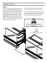
STEP 1. Using case blueprints, measure off and
mark on the fl oor the exact dimensions of where
the cases will sit. Snap chalk line for front and
back positions of base rail or pedestal. Mark the
location of each joint front and back. Find the
highest point throughout the lineup. FLOORS
ARE NORMALLY NOT LEVEL! Determine the
highest point of the fl oor; cases will be set off
this point. All cases in the entire lineup must be
brought up to the highest level of the case sitting
at the highest point in the lineup.
< 1’
Do not use bolts to pull cases together.
It is the contractor’s responsibility to install
case(s) according to local construction and
health codes.
ATTENTION
INSTALLER
STEP 2. Set fi rst case over the highest part of
the fl oor and adjust legs so that case is level.
STEP 3. Set second case within one foot (1’) of
the fi rst case. Keep the supports along the length
of the case and far end of case. Level case to
the fi rst using the instructions in step one.
Summary of Contents for SHVSV Series
Page 9: ...9 Joint Trim Pack list ...
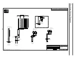
Page 20: ...20 Electrical Wiring Diagram 0 0 0 1 0 0 0 0 2 0 0 3 0 0 1 1 1 1 1 ...
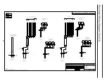
Page 21: ...21 Electrical Wiring Diagram Cont d 0 1 1 1 2 0 1 1 0 1 1 3 0 1 1 4 0 1 1 2 2 2 2 ...
Page 24: ...24 0 1 1 1 2 0 1 1 0 1 1 2 3 0 1 1 4 0 1 1 2 2 2 2 2 2 2 2 Electrical Wiring Diagram Cont d ...


