background image

Rev. 0108

7

Refrigeration

REFRIGERANT TYPE

The standard refrigerant will be R-22 unless otherwise
specified on the customer order. Check the serial plate
on the case for information.

REFRIGERATION LINES

 LIQUID

SUCTION

3/8"  O.D.

 5/8" O.D.

NOTE: The standard coil is piped at 5/8" (suction); however,

the store tie-in may vary depending on the number of
coils and the draw the case has. Depending on the case
setup, the connecting point in the store may be

5

/

8

", 

7

/

8

", or 1

1

/

8

". Refer to the particular case you are

hooking up.

Refrigerant lines should be sized as shown on the refrig-
eration legend furnished by the store.
Install 

P-traps

 (oil traps) at the base of all suction line ver-

tical risers.

Pressure drop

 can rob the system of capacity. To keep the

pressure drop to a minimum, keep refrigerant line run as
short as possible, using the minimum number of elbows.
Where elbows are required, use long radius elbows only.

CONTROL SETTINGS

See the “Case Specs” section of this guidebook for the
appropriate settings for your merchandiser. Maintain these
parameters to achieve near constant product tempera-
tures. For all multiplexing, defrost should be time termi-
nated. Defrost times should as directed in the Case Speci-
fications section of this guide. The number of defrosts per
day should never change. The duration of the defrost cycle
may be adjusted to meet conditions present at your loca-
tion.
0

°

F / -18

°

C or less air temperature. Adequate performance

is assured by the desired condition of the product in case.

ACCESS  TO TX VALVES & DRAIN LINES

MECHANICAL

 - Remove product from end of case. Remove

product racks. Remove refrigeration and drain access panels
(labeled). TX valve (mechanical only) and drain are located
under each access panel at end of the case.

ELECTRONIC

 - The Electronic Expansion valve master and

slave cylinder(s) are located within the electrical access
panel(s).

ELECTRONIC EXPANSION VALVE

 (OPTIONAL)

A wide variety of electronic expansion valves and case
controllers can be utilized.  Please refer to EEV and con-
troller manufacturers information sheet.  Sensors for elec-
tronic expansion valves will be installed on the coil inlet,
coil outlet, and in the discharge air. (Some supermarkets
require a 4th sensor in the return air).  Case controllers
will be located in the electrical raceway or under the case

THERMOSTATIC EXPANSION VALVE LOCATION

This device is located on the same side as the refrigera-
tion stub.  A Sporlan balanced port expansion valve model
is furnished as standard equipment, unless otherwise speci-
fied by customer.

EXPANSION VALVE ADJUSTMENT

Expansion valves must be adjusted to fully feed the evapo-
rator.  Before attempting any adjustments, make sure the
evaporator is either clear or very lightly covered with frost,
and that the fixture is within 10

°

F of its expected operat-

ing temperature.

MEASURING THE OPERATING SUPERHEAT

1. Determine the suction pressure with an accurate

pressure gauge at the evaporator outlet.

2. From a refrigerant pressure temperature chart,

determine the saturation temperature at the
observed suction pressure.

3. Measure the temperature of the suction gas at the

thermostatic remote bulb location.

4. Subtract the saturation temperature obtained in step

No. 2 from the temperature measured in step No. 3.

3. The difference is superheat.
5. Set the superheat for 5

°

F - 7

°

F.

Multiplexing - Piping of merchandisers operating on the
same refrigeration system may be run from merchandiser
to merchandiser through the end frame saddles provided
for this purpose. DO NOT RUN REFRIGERANT
LINES THROUGH  MERCHANDISERS THAT ARE
NOT THE SAME REFRIGERATION SYSTEM
 as this
may result in poor refrigeration control and compressor
failure.
Line Sizing - Refrigerant lines should be sized as shown
on the refrigeration legend that is furnished for the store
(not furnished by Hussmann). If a legend has not been
furnished, refer to the Hussmann Application Engineering
Manual for guidance.
Oil Traps - P-traps (oil traps) must be installed at the
base of all suction line vertical risers.
Pressure Drop - Pressure drop can rob the system of
capacity. To keep the pressure drop to a minimum, keep
the refrigerant line run as short as possible using a minimum
number of elbows. Where elbows are required, use long
radius elbows only.
Insulation - The suction and liquid lines should be clamped
or taped together and insulated for a minimum of 30’ from
the merchandiser. Additional insulation is recommended
wherever condensation drippage is objectionable.

Summary of Contents for SCSS

Page 1: ... Chino SCSS SCSS SL SERVICE BAKERY REV 0108 Installation Operation Manual SCSS SCSS SL SERVICE BAKERY P N IGSSB SCSS SCSS SL 0108 INSTALLATION OPERATION GUIDE ...

Page 2: ...PPING DAMAGE All equipment should be thoroughly examined for ship ping damage before and during unloading This equipment has been carefully inspected at our fac tory and the carrier has assumed responsibility for safe arrival If damaged either apparent or concealed claim must be made to the carrier APPARENT LOSS OR DAMAGE If there is an obvious loss or damage it must be noted on the freight bill o...

Page 3: ...n inspection Hussmann Chino will acknowledge shortages within ten days from receipt of equipment HUSSMANN CHINO PRODUCT CONTROL The serial number and shipping date of all equipment has been recorded in Hussmann s files for warranty and re placement part purposes All correspondence pertaining to warranty or parts ordering must include the serial num ber of each piece of equipment involved in order ...

Page 4: ...S Plan view Scale 1 2 Elec Stub Up 9 12 1 2 24 1 2 35 1 2 6 1 2 44 1 2 17 1 2 Drain Location 10 48 Variable Front Of Case SCSS SL Summit Cake Self Service Bakery Case Slim Line Remote Self Contained Scale 1 2 12 14 1 4 4 3 4 14 14 3 4 Low Temp Ht 21 1 4 S C Height 15 3 4 Remote Height 5 1 2 Med Temp Height 7 3 4 40 3 4 S C Height 9 3 4 25 1 2 11 3 4 15 1 4 35 1 4 Remote Height 38 Refrig Stub Up 24...

Page 5: ...ined prior to shipment to insure the closest possible fit when cases are joined in the field When joining use a carpenters level and shim legs accordingly Case must be raised correctly under legs where support is best to prevent damage to case 1 Check level of floor where cases are to be set Determine the highest point of the floor cases will be set off this point 2 Set first case and adjust legs ...

Page 6: ...draining 3 Always provide as much down hill slope fall as possible 1 8 per foot is the preferred minimum PVC pipe when used must be supported to main tain the 1 8 pitch and to prevent warping 4 Avoid long runs of condensate drains Long runs make it impossible to provide the fall necessary for good drainage 5 Provide a suitable air break between the flood rim of the floor drain and outlet of conden...

Page 7: ...t coil outlet and in the discharge air Some supermarkets require a 4th sensor in the return air Case controllers will be located in the electrical raceway or under the case THERMOSTATIC EXPANSION VALVE LOCATION This device is located on the same side as the refrigera tion stub A Sporlan balanced port expansion valve model is furnished as standard equipment unless otherwise speci fied by customer E...

Page 8: ...0V 60 Hz electrical supply PIPING For merchandisers with electric defrost the suction and liquid lines should be clamped or taped together and insulated for a minimum of 30 feet For models with KOOLGAS defrost suction and liquid lines should not contact each other and should be insulated separately for a minimum of 30 feet With either type defrost additional insulation for the balance of the liqui...

Page 9: ... the case WIRING SERIAL PLATE AMPERAGE Field Wiring must be sized for component amperes stamped on the serial plate Actual ampere draw may be less than specified Field wiring from the refrigeration con trol panel to the merchandisers is required for refrigera tion thermostats Most component amperes are listed in the Case Specs section but always check the serial plate ASHRAE COLOR CODE NOTE All ot...

Page 10: ...ll parameter settings factory Normal operation Normal operation Normal operation Alarm relay not Alarm Room temp Room temp Set value Change Change Change Set value Room temp Room temp Power off Power on Room temp Room temp Room temp Room temp Room temp Alarm code Fault code Alarm code Fault code Room temp Room temp Defrost operation Defrost sensor temp What to do Initial controller Read or change ...

Page 11: ...temp setting differential 2 A01 0 K 50 K 5 K Lower deviation below temp setting 2 A02 0 K 50 K 5 K Temperature alarm delay A03 0 min 90 min 30 min Door alarm delay A04 0 min 60 min 30 min Compressor Min ON time c01 0 min 15 min 0 min Min OFF time c02 0 min 15 min 0 min Cut in frequency on sensor fault 3 c03 0 100 0 Defrost Defrost method EL GAS d01 EL Defrost stop temperature d02 0o C 25o C 6o C I...

Page 12: ...e product to extend beyond the recommended load limit Air dis charge and return air flue must be unob structed at all times to provide proper refrig eration 6 There are vents located at the base of the front of the glass just above the front rail These vents supply a continuous gentle flow of air across the front glass which inhibits condensation Do not place any signs or other restrictive objects...

Page 13: ... may shatter and cause serious injury Allow glass surfaces to warm first NON GLARE GLASS The high optical clarity of this glass is possible due to spe cial coatings on the glass surface itself To preserve this coating and the optical clarity keep the glass clean Windex or Glass Plus are the only solutions recom mended to be used to clean the non glare glass The dam age to the glass from improper c...

Page 14: ...ype Fan Blade Defrosts Electrical Load Amps 115 VAC Condensing Unit Data Btu Hr Temperatures F Speed Settings Size in Evap Motors per day Evap Fans Case Case Defrost Glass Set PSI Size Voltage Ampacity Length Ft Total Evap Prod Disch CFM F pitch Fans Qty Length Qty Fans Warmer Lights Heater Heater Out In HP VAC SCSS M MediumTemperature 4 650 2 600 20 40 30 200 Optional Forced Air 4 Axial 2 30 2 0 ...

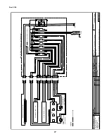
Page 15: ...Lic 644406 Revisions No Description Checked By By File Location Boris Kasrel BJK Sheet of W8000001mnl H WiringSchematics NewWiringDiagrams BOM Prod Refrigerated Medium Temp Self Service Desplay SCSS M Remote Off Cycle Defrost Wiring Diagram 00 00 00 1 1 115V M M M M Anti Sweat Heater Evaporator Fans Glass Heater J BOX Temp Sensor to Temp Defrost Controller 115V 1Ph 60Hz 2 5A ...

Page 16: ...tics In Work 495 01 880 03 29 01 W8100001mnl Refrigerated Low Temp Self Service Display SCSS L E Remote Electrical Defrost Wiring Diagram 1 1 115V 208 230V M M M M Klixon 20420L15 013 302 L40 1 5 Q00VA Anti Sweat Htr 85W 115V Htr Shut Off Evaporator Glass Htr 60W 115V 2 208 230V Finned Defrost Htr Temp Sensor to Temp Defrost Controller J Box SCSS L KG Remote Kool Gas Defrost Legend controls lines ...

Page 17: ...0002mnl Refrigerated Low Temp Self Service Display SCSS L KG Remote Kool Gas Defrost Wiring Diagram 1 1 115V 208 230V M M M M Klixon 600 22 0010 20420l28 229 89 L20 1 5 R98A Klixon 20420L15 013 302 L40 1 5 Q00VA Anti Sweat Htr 85W 115V Fans Shut Off Htr Shut Off Evaporator Glass Htr 60W 115V 208 230V Finned Defrost Htr Temp Sensor to Temp Defrost Controller J Box SCSS L KG Remote Kool Gas Defrost ...

Page 18: ...5V 208 230V M M M M Anti Sweat Htr 85W 115V Evaporator Glass Htr 60W 115V 2 208 230V Finned Defrost Htr J Box SCSS L E S C Low Temp Self Contained ElectricalDefrost Legend controls lines 12 orange 12 black 12 orange 12 black 12 black 12 white 12 green EKC 201 12V 12 14 13 15 16 17 8 9 10 11 2 4 1 3 7 5 6 Temp Probe Defrost Termination Temp Probe Evap Temp High Low Pressure Safety 208 230 1Ph Conde...

Page 19: ...stallation of thesystemwhichdispensescondensatewastethrough an air gap into the building indirect waste system 1 4 The installer should perform a complete start up evaluation prior to the loading of food into the refrigerator which includes such items as a Initial temperature performance Coils should be properly fed with a refrigerant according to manufacturer s recommendations b Observation of ou...

Page 20: ...ights or other high intensity lighting directed onto the product 7 Are there unusual draft conditions from heating air conditioning ducts open doors etc 8 Is there exposure to direct sunlight 9 Are display signs blocking or diverting airflow 10 Are the coils of the refrigerator iced up 11 Is the store ambient over 75 F 55 RH as set forth in ASHRAE Standard 72 and ASHRAE Standard 117 12 Are the she...

Page 21: ...on refriger ated areas e Display and storage equipment doors should be kept closed during periods of inactivity f Minimize the transfer time of perishables from storage to display g Keepmeatunderrefrigerationinmeatcuttingand processing area except for the few moments it is being handled in processing When a cut or tray of meat is not to be worked on immediately the procedure should call for return...

Page 22: ...IGSSB SCSS SCSS SL 0108 22 ...

Page 23: ...under this warranty shall be limited to a period not to exceed five years from date of factory shipment On Hussmann refrigeration systems an additional 4 year extended warranty for the motor compressor assembly is available but must be purchased prior to shipment to be in effect Hussmann reserves the right to inspect the job site installation and reason for failure The motor compressor warranties ...

Page 24: ...r particular unit They can be found on a small metal plate on the unit Please note them below for future reference MODEL SERIAL NUMBER Chino Additional copies of thispublication may be obtained by contacting Hussmann Chino 13770 Ramona Avenue Chino California 91710 909 628 8942 FAX 909 590 4910 800 395 9229 Service Record Last service date By ...

Reviews: