RLTI
with
Innovator Doors
Technical Data Sheet
2 of 6
HUSSMANN CORPORATION, Bridgeton, MO 63044-2483 U.S.A.
Front
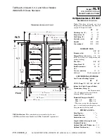
5-Door Shown
Tall Reach-in Island
2, 3, 4, & 5 Door
10/2004
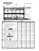
Engineering Plan Views
RLTI
Plan View
D
A
B
C
10
3
/
8
(264)
6
(152)
(see note *)
Water Seal
(see note **)
71
3
/
8
(1814)
43
1
/
4
(1099)
78
3
/
8
(1991)
Refrigeration
Outlet
Bottom Front
Support
Waste Outlet
Front Relay & Terminal
Block Location
Skid/External Base
48
(1219)
68
(1727)
Electrical Wireway
Refrigeration
Outlet
Electrical Wireway
Rear Relay & Terminal
Block Location
74
3
/
4
(1899)
35
1
/
8
(892)
81
(2058)
62
(1575)
Dimensions shown as in. & (mm).
Serial Plate attached to top left front of each case.
2 Dr
3 Dr
4 Dr
5 Dr
General
(A)
Case Length
(without ends or partitions)
62 (1575)
92
1
/
2
(2350)
122
7
/
8
(3121) 153
3
/
8
(3896)
Maximum O/S dimension of case back to front
81 (2068)
81 (2068)
81 (2068)
81 (2068)
(Includes bumpers and handles)
Back of case to rear of splashguard
74
3
/
4
(1899)
74
3
/
4
(1899)
74
3
/
4
(1899)
74
3
/
4
(1899)
Width of Skidrail
4
1
/
2
(114)
4
1
/
2
(114)
4
1
/
2
(114)
4
1
/
2
(114)
Width of Bottom Front Support
6 (152)
6 (152)
6 (152)
6 (152)
Stub-up area between front skidrail and splashguard
6
3
/
8
(161)
6
3
/
8
(161)
6
3
/
8
(161)
6
3
/
8
(161)
Electrical Service
(B)
RH end of case to center of fathest front knockout
56
7
/
8
(1444)
87
3
/
8
(2219)
117
3
/
4
(2991)
148
1
/
8
(3764)
Back O/S of case to center of front knockout
43
1
/
4
(1099)
43
1
/
4
(1099)
43
1
/
4
(1099)
43
1
/
4
(1099)
RH end of case to center of nearest rear knockout
2
3
/
4
(70)
2
3
/
4
(70)
2
3
/
4
(70)
2
3
/
4
(70)
Back O/S of case to center of rear knockout
10
3
/
8
(264)
10
3
/
8
(264)
10
3
/
8
(264)
10
3
/
8
(264)
* NOTE: Electrical Field Wiring Connection Point is at terminal. Front and rear are wired separately.
Waste Outlet
(C)
Right end of case to center of waste outlet
23
3
/
4
(603)
54
1
/
4
(1378)
46
1
/
4
(1175)
76
5
/
8
(1946)
Back O/S of case to center of waste outlet
71
3
/
8
(1814)
71
3
/
8
(1814)
71
3
/
8
(1814)
71
3
/
8
(1814)
Water Seal
Edge of water seal to center of waste outlet
11 (279)
11 (279)
11 (279)
11 (279)
Outside diameter of drip piping
1
1
/
4
(32)
1
1
/
4
(32)
1
1
/
4
(32)
1
1
/
4
(32)
** NOTE: Field installed water seal outlets, tees, and connectors are shipped with case
Refrigeration Outlet
(D)
RH end of case to center of front refrigeration outlet
7
1
/
4
(184)
7
1
/
4
(184)
7
1
/
4
(184)
7
1
/
4
(184)
RH end of case to center of rear refrigeration outlet
54
3
/
4
(1391)
85
1
/
4
(2166)
115
5
/
8
(2937)
146
1
/
8
(3712)
Back O/S of case to center of front refrigeration outlet 43
1
/
4
(1099)
43
1
/
4
(1099)
43
1
/
4
(1099)
43
1
/
4
(1099)
Back O/S of case to center of rear refrigeration outlet
35
1
/
8
(892)
35
1
/
8
(892)
35
1
/
8
(892)
35
1
/
8
(892)
Outside bottom front supports from end of case
6
3
/
4
(170)
6
3
/
4
(170)
6
3
/
4
(170)
6
3
/
4
(170)
Center bottom front support from Centerline
24 (610)
24 (610)
24 (610)
24 (610)
Distance between Center and Outside supports will vary
Top piping is standard in the RLTI case.
Approximate Case Weight –
lb (kg)
(without ends or partitions)
1500 (680)
2300 (1043)
3040 (1379)
3800 (1724)


