background image


INTRODUCTION –  
 
             The Gim-6 is a low temperature, 
self-contained cabinet designed for pre-
packaged ice cream or ice cream novelties 
at below freezing temperatures.  Design 
features include self-closing glass  doors, 
efficient foamed in place non-CFC ins ula-
tion, low rail height, from both sides, and 
a balanced refrigeration system for en-
ergy saving performance       
 
INSPECTION –  
 
              Upon receipt of the cabinet, care-
fully examine the crating for damage.  If 
crate is damaged, make a note on the de-
livery  ticket before signing.   Carefully re-
move shipping crate and examine cabinet 
for  “concealed” damage.   If damage  is 
found, contact the delivery carrier imme-
diately and have his  agent prepare an in-
spection report for the purpose of filing  a 
claim.  THIS IS Y OUR RESPONSIBIL-
ITY.   
 
LOCATION –  
 
              Avoid locating the case where di-
rect sunlight would shine into the fixture 
or where drafts from air conditioning 
grills, fans, and open doors could effect its 
operation. 
 
CLEARANCE –  
 
              Because this condensing unit is  

located at the bottom of the cabinet, a 
three (3) foot clearance should be allowed 
in front of the louvered access panel to 
provide free air movement to  and from 
the condenser for maximum operating ef-
ficiency. 
 
INSTALLATION and START-UP –  
 
SKID –  
 
             The skid should be left on the unit 
until it is  near its final location.  The skid 
provides protection for both cas e and 
floor.  The skid is removed by removing 
the bolts holding the skid clamps to the 
case base, then sliding the cas e off the 
skid.  A “mule” bracket is built in the end 
of the cabinet base frame for this purpose. 
 
LEVELING and SEALING –  
 
             Proper drainage of the evaporator 
condensate water requires the cabinet to 
be properly leveled.  This means left to 
right as well as front to back. 
 
             The case can be leveled using the  
leveling screws in the bottom of the case 
or by shimming under the cabinet base 
frame.  The self-closing doors  require the 
cabinet to be properly leveled.  End to end 
leveling will make the doors close with 
uniform speed and tightness.  Once level 
the case should be sealed to the floor as 
shown in the following drawing, using an 
NSF approved material such as  General 


Summary of Contents for GIM

Page 1: ...LF CONTAINED FOR Pre Packaged Ice Cream and Ice Cream Novelties P N OII GIM January 2006 First Call for help US and Canada 1 800 922 1919 Soporte Tècnico y Asistencia Mèxico 01 800 522 1900 For a Service Network Locator and other Information visit us at www hussmann com select Worldwide Locations ...

Page 2: ...ns Dimensions Electrical and BTU Capacity 6 General Upkeep Care and Cleaning 6 Routine Maintenance 6 Operation and Maintenance Power Switches 7 Temperature Control Thermometer and Electrical Box 7 8 Defrost Time Clock 8 Defrost Heater Thermostat 9 Defrost Heater Replacement 9 Lighting 9 Condensate Heater 9 Expansion Valve Adjustment 10 Refrigeration 10 Leak Testing 10 11 Evacuation 11 Operational ...

Page 3: ...Shooting Chart 12 13 Electrical Components 14 Troubleshooting Lights 15 Warranty and Parts Information 15 Ordering Replacement Parts 15 16 Warranty Parts Procedure Compressor Replacement Procedure ADDENDUM 06 18 03 Evaporator Fan Blades 17 ...

Page 4: ... this condensing unit is located at the bottom of the cabinet a three 3 foot clearance should be allowed in front of the louvered access panel to provide free air movement to and from the condenser for maximum operating ef ficiency INSTALLATION and START UP SKID The skid should be left on the unit until it is near its final location The skid provides protection for both case and floor The skid is ...

Page 5: ...run onto the floor GLASS DOORS The doors are made of tempered heat reflective glass The doors mount in the aluminum top canopy The bottom tracks are provided with wipe outs for cleaning purposes The doors are self closing and are supported by rollers that ride on the upper track The upper track has cut out areas to insert the door rollers up into The door spring is then slipped over a clip at the ...

Page 6: ...ws over the top of the product and is returned through the return air duct The interior of the cabinet has load line markings showing how high product can be loaded in the cabinet without affecting the air curtain White epoxy coated wire baskets are provided for the product and they are designed to fit below the load line DO NOT LOAD PRODUCT ABOVE THE LOAD LINE AS IT WILL ADVERSELY AFFECT CABINET ...

Page 7: ... 404a Check the serial plate for specific refrigerant used CARE AND CLEANING To insure good sanitation appearance and minimum maintenance the cabinet should be cleaned and washed regularly as use de mands Clean with a mild detergent and warm water DO NOT USE AN ABRASIVE CLEANER OR STEEL WOOL AS THEY WILL MAR THE FINISH ROUTINE MAINTENANCE Under normal conditions after the cabi net is installed and...

Page 8: ...roximately 10ºF with a 5ºdifferential The temperature should be checked with a thermometer other than the case thermometer after it is running to insure that the case is running at the proper tem perature for the product THERMOMETER The thermometer is located in one of the interior corners of the cabinet The ther mometer will probably need resetting to re flect the proper case temperature Using a ...

Page 9: ...ottom louvered panel and the electrical box cover The cabinet supply breakers should be disconnected before removing the cover DEFROST TIME CLOCK The timer is factory pre set for two defrost cycles per 24 hours at 6 00 a m and 6 00 p m with a 40 minute failsafe This means there are 4 pins in the time face The timer must be adjusted to the proper time of day when the cabinet is started The timer is...

Page 10: ...d on the underside of the upper canopy The tubes are sleeved to maintain proper heat around the bulb for maximum light inten sity and to protect the product in case of breakage The tubes can be replaced without removing the doors To replace twist the bulb and slide the prongs clear of the lampholder When reinstalling this type of bulb be sure the prongs on the bulb twist and lock into place There ...

Page 11: ...nce of probes turn the valve stem clockwise With this adjustment during a portion of the hunting the temperature differences between the two probes may be less than 3ºF or at times as low as 0ºF Make ad justments of no more than one half turn of the valve stem at a time and wait for at least fifteen adjustments Replace and tighten cover of the valve stem REFRIGERATION As stated previously the GIM ...

Page 12: ...refrigerant into the system until the pressure is above 0 PSIG Always charge the refrigerant line into the system through a new drier in the charging manifold line A 16 cubic inch drier is sufficient for this purpose 4 Repeat steps 2 and 3 two more times the third time evacuating the system to 500 mi crons OPERATIONAL DATA The following is typical data for GIM 6 based on lab tests and may vary und...

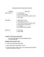
Page 13: ...arm case condition Put a suction compound gauge on the compressor suc tion valve start the compressor If the pressure needs to be reduced turn the ad justment screw clockwise or counter clockwise to raise the pressure DO NOT SET THE VALVE BASED ON THE NAMEPLATE AMPERAGE RATING AS THE PRESSURE SETTING WILL BE TOO HIGH AND THE COMPRES SOR WILL NOT START PROPERLY TROUBLE SHOOT CHARTS TROUBLE PROBABLE...

Page 14: ...ling on overload 5 Check power 6 Condenser dirty 6 Clean 7 Honeycomb iced up 7 Clean Compressor runs continuously product too cold 1 Defective control 1 Replace 2 Control feeler tube not in positive contact 2 Assure proper contact 3 Short on refrigerant 3 Leak check change drier evacuate and recharge Compressor will not start no noise 1 Blown fuse or breaker 1 Replace fuse or reset breaker 2 Defec...

Page 15: ...ve condenser 6 Replace 7 CRO not set properly 7 Reset to 12 psi Icing condition in drain pan under evaporator 1 Low voltage 1 Check voltage at compressor 2 Cabinet not level 2 Check front to rear leveling adjust legs accordingly 3 Defective defrost heater 3 Replace ELECTRICAL COMPONENTS Compressor KAA2 0075 IAA R 502 KAAB 007E CAA R 404a Condenser Fan Motor EMS ESPL25EM1 Evaporator Fan Motor Morri...

Page 16: ...nd proper contact 4 Bulb replacement may be necessary 5 Check voltage 6 New bulbs tend to flicker until used Ballast hums 1 Check voltage 2 Replace ballast WARRANTY AND PARTS INFORMATION PLEASE READ CAREFULLY TO ASSURE PROMPT AND ACCURATE SERVICE ORDERING REPLACEMENT PARTS 1 Contact your nearest Hussmann Distributor 2 Always specify model and serial number of cabinet 3 If correct part number is no...

Page 17: ...the shipment of the wrong part or a delay in shipment COMPRESSOR REPLACEMENT PROCEDURE Replacement compressors will not be shipped from the Hussmann factory They may be obtained from you nearest Copeland Wholesaler Your wholesaler will replace free of charge any compressor found to be defective within twelve months of installation not to exceed twenty months from the date of manufacture as determi...

Page 18: ...ion pressure it is important that the evaporator fan blades are mounted as shown in the illustration below When properly mounted the embossed rib should be facing out as you look at the blade The words Face To You in red ink should also be visible as you look at the blade Embossed rib ...

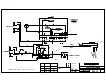
Page 19: ...T CONDENSER FANS COMPRESSOR HEATER HONEYCOMB ANGLE HEATERS BLK EVAPORATOR DEFROST BLK DEFROST STAT POWER CORD GRN TEMPERATURE CON TROL T 3 32 24 23 T 4 20 26 BLK BLK 2 BRN DRAIN CANOPY BLU 15 BLK 1 1 1 T 1 5 2 3 T 2 10 7 4 9 8 31 6 BASE HEATER 12 Gloversville N Y 12078 1 64 SPACING TITLE HOLE LOCATION ANGULAR DECIMAL FRACTIONAL OTHERWISE SPECIFIED TOLERANCES UNLESS M100 2100 REV 10 97 DWG NUMBER R...

Page 20: ...COMPRESSOR HEATER HONEYCOMB ANGL E HEATERS BLK EVAPORATOR DEFROST BLK DEFROST STAT POWER CORD GRN TEMPERATURECONTROL T 3 32 24 23 T 4 20 26 BLK BLK 2 BRN DRAIN CANOPY BLU 15 BLK 1 1 1 T 1 5 2 3 T 2 10 7 4 9 8 31 6 BASE HEATER 12 Gloversville N Y 12078 1 64 SPAC ING TITLE HOLE LOCATIO N ANGULAR DECIMAL FRACTIONAL OTHERWISESPECIFIED TOLERANCES UNLESS M100 1543 1 REV 10 97 DWG NUMBER R CHECKED DRAWN ...

Reviews: