background image

English-

61

TROUBLESHOOTING

Troubleshooting

Engine

Check section 8 of the Kawasaki Service Manual.

The above section contains a troubleshooting guide for engine and auxiliary systems. It also has a special 
section on troubleshooting the starter motor.

Wiring Harness

Symptom: The starter motor works but the engine does not turn over. 

Suggested procedure:

1.

Check the fuel level and the position of the fuel valve lever.

2.

If OK, disconnect the hose, hold the end in a container and crank the engine. If no fuel comes out, 
the fuel pump is faulty or the line is blocked. If fuel does come out;

3.

Remove the air filter cover and air filter. The fuel valve can be seen in front of the carburetor. With 
the seat switch depressed, hold a finger against the valve and turn the ignition switch to RUN. A 
sharp click will be felt if the valve opens (the carburetor will then be getting fuel). If not;

4.

Disconnect the main harness from the engine. Locate the red and violet wires in the main harness 
connector. Attach the red (+) lead from a voltmeter to this connector, and ground the black (-) lead 
to the mower chassis. With an operator in the seat and the ignition turned to RUN, the voltmeter 
should register 12 volts. If it does, the fuel valve is faulty. If there is no voltage, the problem may be 
in the harness wires, the connectors or the ignition switch. 

Symptom: The starter motor does not work.

Suggested procedure:

1.

Check that the brake lever is in the on position, that the blade engagement switch is pushed in, 
that the motion control levers are in the neutral slots and that there is someone on the driver’s 
seat. If all correct; 

2.

Check the 20-amp fuse. If OK;

3.

Check the battery for charge (should be 12 to 13 volts) and that the battery cables are making 
good contact at both ends. If OK;

4.

With all levers and switches properly positioned for start and an operator on the seat, hold index 
finger and thumb against the start relay, and turn the ignition switch to RUN. A sharp click should 
be felt in the relay. If not, change the relay and try again. If a click is felt;

5.

Check that all harness connections to the various switches and the engine are properly 
connected. If all OK;

6.

Disconnect the yellow lead from the starter’s contactor; attach the red (+) lead of a voltmeter to 
this wire, and ground the black (-) lead to the mower chassis. With all levers and switches properly 
positioned for start and an operator on the seat, turn the ignition to RUN. The voltmeter should 
read 12 to 13.5 volts. If there is no voltage, the harness may have a broken wire, a connection in a 
cable connector may be damaged or a switch broken/incorrectly set.

Symptom: The ignition fuse blows with the ignition switch at RUN, but does not blow if the engine 
connector is disconnected.

Suggested procedure:

1.

With engine connector connected, disconnect the seat and brake switches and the blue and violet 
lead from the hour meter. Does the 20-amp ignition fuse still blow when the ignition is now turned 

Summary of Contents for ZTH5223

Page 1: ...Workshop manual ZTH English ...

Page 2: ...Svenska 31 ...

Page 3: ...oke Wire 32 Fuel tank 33 Adjusting Motion Control Lever Linkages 34 Adjusting Motion Control Lever Spring back 34 Adjusting the Park Brake 34 Mower Deck 35 Spindle Blade Bearings 36 Sharpening and Balancing Blades 37 Setting the Mower Deck 38 Deck Belt 38 Hydraulic Pump Belt 40 Front Wheel Bearings 41 Electrical System 43 Troubleshooting 43 Wiring Assembly 43 Battery 46 Fuses 46 Relays 47 Starter ...

Page 4: ...English 2 ...

Page 5: ...t direct the air stream towards themselves or any other person Air may penetrate the blood stream and cause life threatening damage Use hearing protectors when test driving After test driving do not touch the muffler before it has cooled down danger of burns This especially applies if the ride on mower has a catalytic converter If consumed the lining on and in the catalytic converter element can d...

Page 6: ...ies During certain maintenance and service operations it is required that the mower be rendered incapable of starting This is to prevent injury to those working on or standing near the mower Hydrostatic braking may be lost if there is a failure in the hydrostatic drive Certain solvents and cleaning agents are flammable Do not use them whenever there is a less dangerous alternative Never use flamma...

Page 7: ... a danger of material damage especially if the special instructions are not followed It is also used where it is judged that there is a danger of incorrect handling or incorrect assembly fitting WARNING Xxxxxxx xxxx xxxxxxxx xxx x xxxx xxxxxx xx IMPORTANT INFORMATION Xxxxxxx xxxx xxxxxxxx xxx x xxxx xxxxxx xx Park brake Do not stand here Battery acid is corrosive explosive and flammable CE conform...

Page 8: ...rial measurement are used on these Those working on the mower must have ready access to socket wrench sets and open end wrenches of the following sizes 3 8 7 16 1 2 9 16 5 8 11 16 3 4 The following are also required Torque wrenches 12 Nm 110 Nm 15 16 socket for torque tightening of blade bolts 7 8 open end wrench or combination wrench for torque tightening of hydraulic lines A set of small imperia...

Page 9: ...ft lb Cutting height Adjustable 38 mm 1 5 to 152 mm 6 in 64 mm 0 25 increments Adjustable 38 mm 1 5 to 152 mm 6 in 64 mm 0 25 increments Blade engagement Warner Mag Stop Electromagnetic clutch Warner Mag Stop Electromagnetic clutch Slip torque clutch 271 Nm 200 ft lb 271 Nm 200 ft lb Clutch coil resistance 1 74 1 93 ohms at 23 C 68 F 1 74 1 93 ohms at 23 C 68 F Supply voltage clutch 12 14 V 12 14 ...

Page 10: ...ar tires Carlisle 24 X 12 00 12 Tubeless Turf Master Carlisle 24 X 12 00 12 Tubless Turf Master Tightening torque lug nuts 100 Nm 75 ft lb 100 Nm 75 ft lb Front tires Carlisle 13 X 5 00 6 Tubeless Carlisle 13 X 5 00 6 Tubeless Electrical system 12 V with 15 A charging system 12 V with 15 A charging system Fuel capacity 44 litres 11 4 US Gal 22 litres tank 44 litres 11 4 US Gal 22 litres tank Seat ...

Page 11: ...ATA 7 16 70 Nm 52 ft lb 70 Nm 52 ft lb 1 2 110 Nm 80 ft lb 110 Nm 80 ft lb Accessories BioClip adapter Optional Optional Foot controlled mower deck lift Optional Optional Deluxe seat Optional Optional Model ZTH5223 ZTH6125 ...

Page 12: ...English 10 TECHNICAL DATA ...

Page 13: ... Check that the engine has the right quantity of oil 9 Check that the hydraulic tank has the right quantity of oil 10 Adjust the position of the motion control levers 11 Fuel the mower and open the gas valve 12 Connect exhaust fume extraction 13 Start the engine 14 Vent the hydraulic system 15 Check that there is drive to both wheels 16 Check mower deck settings 17 Check The park brake safety swit...

Page 14: ...p air filter 2 Check the oil level in the hydraulic system 3 Check tire pressure 4 Lubricate the mower deck s belt tensioner 5 Lubricate the hydraulic pump s belt tensioner 6 Check clean the engine s cold air intake 7 Clean the air cleaner s pre filter Oil foam 50 Hour Service 1 Carry out a 25 hour service 2 Clean change the air cleaner s filter cartridge paper filter Perfom more reqularly in dust...

Page 15: ...8 Clean the engine and transmission cooling fins 9 Clean and check if the air filter s paper cartridge needs changing every 200 hours 300 Hour Service 1 Inspect the machine Reach agreement with the customer on what additional work is to be carried out 2 Carry out a 25 hour service 3 Carry out a 50 hour service 4 Carry out a 100 hour service 5 Change the oil and the filter in the hydraulic system 6...

Page 16: ... 100 hours 5 Change the engine s oil filter 200 hours 6 Change the oil and the filter in the hydraulic system 7 Check adjust the cutting height regulator 8 Check adjust the park brake 50 hours 9 Clean change the spark plugs 100 hours 10 Change the fuel filter in the fuel line 100 hours 11 Clean the cooling fins 100 tim 12 Check the play in the engine valves 300 hours 13 A 300 hour service to be ca...

Page 17: ...lts nuts etc Start engine and blades check for abnormal noise Clean the underside of the mower deck Check hydraulic system oil level 22 Check the condition of belts pulleys etc 38 Check for any damage Check tire pressure 20 Clean thoroughly around the engine Clean thoroughly around the hydraulic system 53 Clean thoroughly around belts pulleys etc Lubricate mower deck belt tensioner Lubricate belt ...

Page 18: ...cutting height regulator 38 Clean the air cleaner s pre filter Oil foam Clean the air cleaner s filter 2 paper filter Change the motor oil 1 22 Change the hydraulic oil every 300 hours 56 Change the engine s oil filter every 200 hours Clean change the spark plugs Change the fuel filter in the fuel line Clean the cooling fins Check the play in the engine valves 4 Change the air cleaner s pre filter...

Page 19: ...r to enter all service work in the Service Log at the back of the Operating Instructions Record details of any major repairs Enter the meter reading and date Stamp and sign the stamp field In your customer register make a note of the work that has been carried out ...

Page 20: ...English 18 DELIVERY AND DEALER SERVICE ...

Page 21: ...marketing and when ordering spare parts When supplying a mower you should also give the customer all information necessary for the safe operation and care of the machine Pay particular attention to informing the customer about Safety instructions Mower controls Checking oil levels and the oil to be used when topping up The first oil change after the running in period The necessity and advantages o...

Page 22: ...e is to be reported to the transport company in the normal way The packaging is not to be returned Delivery Service 1 Charge the battery The mower is normally delivered with a charged battery topped up with electrolyte 2 Raise the rear of the mower until it is clear of the baseplate and the rear wheels can rotate freely Hold firmly in position using blocks or jack stands 3 With the valves facing o...

Page 23: ...t possible distance between them The bolt heads should be on the inside i e towards the seat back and washers and nuts on the outside Armrests bolts washers and anti slip nuts are packed in a plastic bag accompanying the mower 9 Check the engine oil level With the mower standing on a flat surface check the engine oil level Unscrew the dipstick and pull it out Wipe the dipstick dry and push it back...

Page 24: ... be 19 25 mm below the top of the tank Top up if necessary 11 Adjust the motion control levers a Set the seat longitudinally in a comfortable position and swing the levers into the drive channel b Hold one of the levers at a comfortable midpoint and tighten the retaining bolts c Hold the other lever as far forward as the first and tighten the bolts ADD FULL ADD FULL 8009 159 Engine dipstick 20 C 4...

Page 25: ...ntrol levers in the neutral position both rear wheels are stationary 19 Remove the blocks supporting the back end 20 Raise the mower deck to its highest position 21 Raise the back of the baseplate and drive the mower forwards and off 22 Check mower deck settings as per the instructions see Adjusting Motion Control Lever Linkages on page 34 WARNING Gasoline is highly flammable Take great care 8011 ...

Page 26: ...in neutral and the park brake disengaged the mower does not move on flat ground Increase the throttle setting the mower must still remain stationary Check that the park brake operates correctly Check that the mower moves straight forwards backwards when both motion control levers are simultaneously moved an equal distance forwards backwards Check that the mower turns normally when driving forwards...

Page 27: ...ependent adjustment of the speed and direction of each rear wheel The front wheels are free to turn in whichever direction is most suitable The mower deck is mounted underneath the mower and is supplied with a side discharge chute as standard The range of accessories includes a BioClip kit of guide plates and blades for mounting beneath the mower deck casing Mower Identification Each mower is indi...

Page 28: ...p identifiers are located on a bardcoded decal This is sited on the left side of the pump housing The decal gives The pump type code BDP 10 The pump serial number The hydraulic motor identifiers are located on a round metal plate This is sited on the end of the motor housing The plate gives The hydraulic motor type code and model The hydraulic motor serial number 8009 205 Engine identification 801...

Page 29: ...h pump The mower can be made to turn or reverse by controling the rate and direction of flow to the hydraulic motors The hydraulic motors control the speed and direction of the drive wheels To swing the mower around its center simply drive one wheel forwards and the other backwards Hydrostatic braking occurs whenever there is no flow of oil from the pumps Instructions for the repair of the hydraul...

Page 30: ...g on their shafts if they hit an immoveable object The discharge chute is on the right side of the mower deck It is spring loaded and can be raised For mulching a BioClip kit is available as an accessory The kit comprises guide plates and BioClip blades It is fitted to the underside of the mower deck The mower deck is suspended to the bottom of the mower via two backward inclined struts and four a...

Page 31: ...front of the starter motor 9 Raise and support the back of the mower on blocks or similar 10 Remove the clip holding the oil drain hose 11 Remove the deck belt and clutch see Electrical System Mower deck clutch 12 Loosen the bolt 2 and twist the clutch tie down 10 aside see the Engine mounts diagram 13 Using a square 1 2 ratchet wrench loosen the pump belt Roll the belt off the pulley on the engin...

Page 32: ...1 2 ratchet wrench to cancel the force exerted by the belt tensioner 6 Fit the washer 6 and mower deck clutch 7 Connect the cable to the connector The tightening torque for the bolt 9 is 67 Nm 50 ft lb With the bolt 9 tightened there should be perceptible play between the clutch and the clutch tie down 10 when the clutch flange is turned by hand Adjust twist the tie down and using the nut 1 tighte...

Page 33: ... starter motor Adjusting the Throttle Wire Adjusting Throttle Lever Tension If there is insufficient throttle lever friction throttle settings can alter while the mower is being operated This can be corrected via the lever s pivot bolt 1 Free the control console and pull forwards 2 Tighten the throttle lever s pivot bolt Checking and Adjusting the Throttle Wire Check that the engine responds to th...

Page 34: ...o start the choke wire upper wire may be incorrectly adjusted To adjust the choke proceed as follows 1 Release the clamping screw that secures the wire casing and set the choke control to maximum choke 2 Check that the throttle wire is attached to the upper lever see the diagram 3 Pull the choke wire casing to the far right and tighten the clamping screw 8011 555 Checking and adjusting the choke w...

Page 35: ... Even when the tank is empty a small amount of fuel may leak out 5 The tank is fitted to the splashguard by a bolt and two studs Remove the bolt 16 and three nuts 10 all with washers 8 and springs 9 located on the underside of the splashguard 6 Remove the bolt 12 and tank spacer located on the inside of the splashguard 7 Lift the fuel tank 2 away Fitting The fitting procedure is the reverse of the...

Page 36: ...4 inch 3 Disengage the parking brake hand lever and check that the spring is still under tension This is important in order to hold the linkage from going over center 4 Repeat steps 2 and 3 on the opposite brake band 5 If the brake band is making noise while in operation rattling squealing etc it may be necessary to readjust the parking brake band 8011 581 Adjusting the park brake Spring 1 8 1 4 S...

Page 37: ...position under the mower 2 Using two lengths of 2 x 4 one towards the edge of each of the deck s short sides support the deck 4 off the ground 3 Grease the pivot pins 50 of the rear bearings with copious amounts of corrosion preventing grease Line up the shaft bearings and slide the pivot pins into place Fit the bolts and nuts 17 5 holding the pivot pins in place see the ZTH mower deck diagram WAR...

Page 38: ...nd the pulley 3 Lock the pulley using a bolt through the hole in the pulley and a holding tool 3 Raise the mower deck to its highest position Lift the front end of the mower and support it on blocks or similar 4 Remove the bolts 12 and nuts 5 and pull downwards to remove the bearing and blade 5 Separate the blade from its bearing Repairing Bearings If there is too much play the bearing 44 can be r...

Page 39: ... vice see diagram and file until sharp Balancing is as follows Fix a mandrel for example horizontally in a screw vice see diagram Push a blade onto the mandrel and check that it is evenly balanced The diagram shows a blade which needs adjusting This blade should be ground at the edge indicated by the straight arrow The fitting procerdure is the reverse of the removal procedure The tightening torqu...

Page 40: ...Adjusting Cutting Height Raise and secure the deck height lever to the transport position 6 Measure from the cutting edge of the blades to the flat level surface The distance should be150 mm 6 Drop and secure the lever at for example the 2 cutting height Measure as above The distance should be 50 mm 2 Deck Belt Check the belt every 75 to 100 hours of operation Inspect carefully for large cracks an...

Page 41: ...sted and that it runs correctly around all the pulleys Belt Tensioning Assembly The belt is automatically tensioned by a spring 18 To cancel the force of the spring use a 9 16 socket on the bolt 33 when removing or fitting the belt Check that there is no abnormal noise indicating that the idler pulley is loose on its shaft If it is loose tighten the bolt 33 or change the idler pulley Check that th...

Page 42: ...ove the old belt 9 Fit the new belt on the crankshaft pulley 10 Swing the idler pulley towards the engine and fit the belt 11 Fit the belt around the pulley on the right looking upwards from below the mower 12 Attach the spring and use a square 1 2 ratchet wrench to cancel the force exerted by the belt tensioner 13 Fit the belt around the left pulley looking upwards from below the mower 14 Check t...

Page 43: ... Remove the grease cap 26 2 Raise and support the front of the mower on blocks or similar 3 Remove the cotter pin 30 4 Remove the castle nut 27 and pulling downwards remove the front fork 5 Remove the upper bearing 28 6 Taking great care not to damage the seal 31 use a hammer and a suitable rod or similar to knock the lower bearing out in a downwards direction Assembling The assembly procedure is ...

Page 44: ...English 42 REPAIRS ...

Page 45: ...ect the engine to the frame harness 13 there is a pigtail This plugs into connector D see diagram above The Kawasaki pigtail is illustrated below 8011 584 ZTH electrical system A To the engine ground bolt B To the solenoid C To the electric clutch D To the pigtail E To the park brake F To motion control lever G To the seat H Console harness J Frame harness 8011 587 Kawasaki pigtail Vio Violet Wht ...

Page 46: ...sh 44 ELECTRICAL SYSTEM The console harness 1 connects the console controls to the frame harness A B C D E F 8011 629 ZTH console harness Blk Black Blu Blue Gra Gray Grn Green Pur Purple Wht White Yel Yellow ...

Page 47: ...nnectors connecting the frame harness 13 to the console harness 1 The engine pigtail page 43 plugs into the Engine Pigtail socket of the frame harness 8011 628 ZTH frame harness Blk Black Blu Blue Gra Gray Grn Green Pur Purple Wht White Yel Yellow ...

Page 48: ...ossible Fuses Refer to the ZTH electrical system diagram The fuses 23 24 plug into a holder on the left of the hydraulic tank They are of the flat pin type commonly used in automobiles There are two active fuses and sockets for two spares Fuse rating and function working along the holder from right to left is 20 A main fuse 7 5 A deck clutch Socket for spare fuse Socket for spare fuse WARNING The ...

Page 49: ...one way only Press each relay down until the body contacts the holder Starter Motor Contactor Changing 1 Disconnect the cable connecting the battery to the chassis To avoid damaging the battery terminals use two wrenches 2 Pull the cables off the contactor 3 Remove the contactor the nuts are under the frame plate 4 Position the new contactor so that the pin for the control cable is towards the cha...

Page 50: ... in the switch and then tighten the nut 7 Remove the key and fit the rubber cap 20 Reinsert the key 8 Reconnect the wires at the back of the ignition switch 9 Refit the control console Hour Meter Refer to the ZTH electrical system diagram Changing 1 Free the control console and pull forwards 2 Disconnect the wires at the back of the hour meter 12 3 Prise the catches apart and remove the hour meter...

Page 51: ...he Supply Voltage See the Troubleshooting section towards the back of this manual Measuring Coil Resistance See the Troubleshooting section towards the back of this manual Troubleshooting Guide See the Troubleshooting section towards the back of this manual Removing 1 Drop the deck to its lowest position 2 Remove the operator s foot plate 3 Using a 9 16 socket on the bolt of the idler pulley loose...

Page 52: ...y adjust twist the tie down Ensure that the cable cannot be damaged and secure it with a cable tie Motion Control Switches These micro switches are difficult to access By pulling the control console forwards it is possible to change the right switch without any other major dismantling However this does require two people When changing the left switch the tubular shafts 31 33 of the motion control ...

Page 53: ...ft Fitting The fitting procedure is the reverse of the removal procedure Pay particular attention to the following Check and position the switches before fitting the tubular shaft Position the switches so that there is a click when the inner flat surface of the arm continuation shaft 5 passes over the outside corner of the tubular shaft s lever mount Check the setting of the linkages see Hydraulic...

Page 54: ...ove the component to be welded e g the muffler or the ignition system Before carrying out welding on any other part of the mower 1 Remove the battery cables 2 Disconnect the connector between the engine pigtail and the frame harness 3 Connect the welding earth lead as near as possible to the point of welding IMPORTANT INFORMATION When performing electric welding on the mower take all necessary pre...

Page 55: ... by the breaking down of the hydraulic oil Corrosive matter produced in the system as a result of oil not being changed in time Old oil tends to be rich in water and other aggressive substances Dirt entering the system during service or repair work e g Contamination during the changing or topping up of oil Dust in the workshop Sealing agents and similar Dirt from storage and handling prior to fitt...

Page 56: ...a hydraulic system However it must be borne in mind that used components sent to a workshop will often be specially inspected and or tested Such components should be dispatched in the condition they were prior to removal Otherwise the true reason for the fault may be difficult to ascertain and testing may give false results Furthermore returned components that have been cleaned may mistakenly be p...

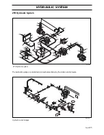
Page 57: ...English 55 HYDRAULIC SYSTEM ZTH Hydraulic System The hydraulic pumps are controlled via mechanical links by the motion control levers 8011 588 ZTH hydraulic system 8011 589 Hydraulic pump linkages ...

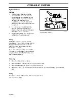
Page 58: ...e changed Filling Fill the tank with clean oil direct from the manufacturer s container For oil type refer to the hydraulic tank decal or the lubrication chart The use of non approved oils can invalidate the warranty The level must be around 19 25 mm 3 4 1 below the top of the tank Vent the system using the air screws on the hydraulic pumps and top up as necessary Removing 1 Drain the hydraulic ta...

Page 59: ...ntal regulations relating to engine oil filters An oil filter chain may be used for removal but not for fitting 1 Screw the filter 3 from the filter head 4 refer to the ZTH hydraulic system diagram 2 Smear the new filter s gasket with clean hydraulic oil 3 Screw on the new filter until the gasket contacts the filter head 4 Manually turn the filter a further one and a half turns Removing 1 Drain th...

Page 60: ... 5 Loosen the two lock screws holding the pump pulley and remove it from its shaft 6 Clean as set out in the instructions 7 Remove the hydraulic lines 21 22 or 23 24 and O rings 34 from both pump and motor 8 Be careful not to damage the cooler when working on the right hydraulic pump Release the ball joint 10 from the pump lever 12 refer to the Hydraulic pump linkages diagram 9 Disconnect the hose...

Page 61: ...rection Turn these nuts far enough to just stop the wheel rotating 7 Move the motion control lever forward then into the neutral position and then into the neutral slot The wheel must stop completely at this point 8 Now move the motion control lever into the reverse position and release it The lever should return to neutral on its own If not the reverse spring detent must be adjusted check below 9...

Page 62: ... Using an extractor if necessary pull the hub off the axle 5 Remove the park brake as a single unit 6 Clean as set out in the instructions 7 Disconnect the hydraulic lines 21 22 or 23 24 and O rings from both the pump and the motor 8 Remove the hydraulic motor from its bracket Dismantling and Assembling Refer to Parker Hydraulics TorqlinkTM Service Procedure for TE Hydraulic Motors Fitting The fit...

Page 63: ...ggested procedure 1 Check that the brake lever is in the on position that the blade engagement switch is pushed in that the motion control levers are in the neutral slots and that there is someone on the driver s seat If all correct 2 Check the 20 amp fuse If OK 3 Check the battery for charge should be 12 to 13 volts and that the battery cables are making good contact at both ends If OK 4 With all...

Page 64: ...in A blown fuse here indicates that the relay is faulty 6 If it has been established that the problem is in one of the safety interlock circuits that the battery is delivering 12 volts and that the main fuse is OK but that the engine will not turn over the brake relay can be easily tested as set out below Engage the brake disconnect the brake relay and attempt to start the engine If the engine now...

Page 65: ... supply voltage at the clutch 1 Turn the engine off 2 Connect the meter leads at the clutch connector 3 Set the meter to read volts 4 Ensure that the wires will not become entangled in the rotating parts of the clutch 5 Start the engine and engage the PTO switch 6 Measure the voltage across the leads at the connectors 7 The voltage should be 12 14 volts DC If the clutch still fails to operate repl...

Page 66: ...oil resistance and supply voltage at the clutch If both are correct electrical system is faulty Repair or replace Rotor armature air gap too Rotor armature wear End of Replace with new MagStop unit large more than useful life 0 125 3 18 mm Brake will not engage Armature brake poles End of useful life Replace with new MagStop unit worn out Contaminated friction Engine oil leak on brake Repair leak ...

Page 67: ...se on shaft Loose mounting bolt not tightened Tighten mounting bolt to to the correct torque specification Mounting bolt too long and Use correct length bolt bottoms on the crankshaft before the clutch bites Mounting washer too thin and Use correct washer deforms when bolt is tightened Shaft bottoms on the clutch Use proper spacer at least1 4 thick Clutch not mounted square Ground drive spacer mou...

Page 68: ...h Adjust the speed regulator Oil level low or oil contaminated Fill to proper level or change oil Excessive loading long grass Raise the cutting height drive more slowly Air trapped in the hydraulic system Aerate the system Bypass loose Tighten bypass Inlet leak Check all connections and hoses for leaks Clogged damaged hydraulic filter Replace filter Unit has no low power Engine RPM low Adjust the...

Page 69: ...r Hydraulic cooler clogged or Replace hydraulic cooler damaged Oil level low or oil contaminated Fill to proper level or change oil Excessive loading long grass Raise the cutting height drive more slowly Air trapped in the hydraulic system Aerate the system Inlet leak Check all connections and hoses for leaks External oil leak Loose connection seal Tighten clean test run Damaged seal or gasket Rep...

Page 70: ... H 6D ...

Page 71: ...Svenska 31 ...

Page 72: ...114 00 80 26 2002W20 H 6D ...

Page 73: ...ltivators Cylinder Lawn Mowers Echo Chainsaws Echo Strimmers Electric Chainsaws Fertiliser Spreaders Garden Blowers Garden Rollers Lawn Rollers Garden Shredders Garden Tractors Garden Vacuums Hayter Lawn Mowers Hedge Cutters Hedgecutters Hover Mowers Husqvarna Chainsaws Kawasaki Brush Cutters Kawasaki Strimmers Lawn Mowers Scarifiers Lawn Tractors Leaf Blowers Leaf Vacuums Petrol Chainsaws Petrol ...

Reviews: