background image

´+H$r¶6C¨

SERVICEJOURNAL

Work done

Date, mileage, stamp, sign

Summary of Contents for SG 13 B

Page 1: ...Operator s manual Please read these instructions carefully and make sure you understand them before using the machine English Rider 11 Rider 13 Rider 11 Bio Rider 13 Bio ...

Page 2: ...Svenska 31 ...

Page 3: ... the machine before using it For servicing other than described in this manual contact an authorised dealer for parts and service Maintenance schedule 21 Dismantling of the machine hoods 22 Checking and adjusting the steering wires 24 Checking and adjusting the brakes 25 Checking and adjustment of throttle wire 26 Replacement of fuel filter 26 Replacement of air filter 25 Checking the fuel pump s ...

Page 4: ...c transmission you should if necessary only tow the machine over short distances and at a low speed otherwise there is a risk of damaging the transmission Intended use This machine is designed solely for cutting grass on conventional lawns and other cleared and leveled ground without obstacles as rocks stumps etc and in conjunction with accessories supplied by the manufacturer even for other speci...

Page 5: ...re The machines type designation The manufacturer s type number The machine s serial number State the type designation and serial number when ordering spare parts The engine number is punched on a plate that is riveted to the fan cover The plate states Model Type Code Please state these when ordering spare parts The transmission s serial number on hydrostatic machines is stated on the barcode deca...

Page 6: ...ift up the cutting unit Put the gear shift hydrostat pedal in neutral Brake If the engine is cold use the choke Start the engine Release the parking brake before driving Drive very slowly without the cutting unit Keep hands and feet away from under the hood when the engine is running Speed limiter pedal forwards Neutral Speed limiter pedal reverse Switch off the engine and take off the ignition ca...

Page 7: ...the area of objects such as stones toys wires etc that may become caught in the blades and be thrown out Look out for the ejector and do not direct it towardsanyone Stop the engine and prevent the engine from being started until you have cleaned the outlet channel Remember the operator is responsible for danger or accidents Never carry passengers The machine is only intended to be used by one pers...

Page 8: ...ossing it Never leave the machine unsupervised with the engine running Always stop the blades apply the parking brake stop the engine and remove the keys before leaving the machine Never allow children or other persons not trained in the use of the machine to use or service it Local laws may regulate the age of the user SAFETY INSTRUCTIONS WARNING Engine exhaust some of its constituents and certai...

Page 9: ...rds if possible Watch out for and avoid driving over furrows holes and bumps It is easier for the machine to overturn on uneven ground Tall grass can hide obstacles Drive slowly Do not turn the wheel sharply Rider 11 Select a low gear so that you will not need to stop to change gear The machine engine brakes even better in low gear Take extra care if any attachments are fitted that can change the ...

Page 10: ...r allow children to operate the machine Be particularly careful near corners bushes trees or other objects that block your view SAFETY INSTRUCTIONS Never allow children to operate the machine Never fill the fuel tank indoors Maintenance Stop the engine Prevent starting by removing the ignition cable from the spark plug or remove the ignition key before making any adjustments or carrying out mainte...

Page 11: ... petrol on your clothing change your clothing Allow the machine to cool before performing any actions in the engine compartment Be especially careful when handling battery acid Acid on the skin can cause serious corrosive injuries In the event of spillage on the skin wash immediately with water Acid in the eyes can cause blindness contact a doctor immediately Take care with battery maintenance Exp...

Page 12: ...The mulching unit should only be used where better quality mowing is required and in known areas Reduce the risk of fire by removing grass leaves and other debris that may have fastened on the machine Allow the machine to cool before putting it in storage Transport The machine is heavy and can cause serious crush injuries Be especially careful when it is loaded in or out of a car or on and off of ...

Page 13: ...ngine is handled by a hydrostatic gearbox which enables stepless variation of the speed Location of the controls 1 Ignition lock 2 Throttle Choke lever 3 Adjustment of cutting height 4 Lifting lever cutting unit 5 Speed control for reversing only on 13 and 13 Bio 6 Speed limiter for driving forwards on 13 and 13 Bio Parking brake on 11 and 11 Bio 7 Parking brake on 13 and 13 Bio Clutch pedal on 11...

Page 14: ...cher mixture of fuel and air which simplifies cold start Clutch pedal The clutch pedal disengages the engine and stops forward movement The blades are not affected by the clutch pedal Brake pedal Parking brake The brake pedal activates a disc brake which is placed on the gearbox and brakes the drive wheels When braking the clutch pedal should also be pushed down to achieve best braking power The b...

Page 15: ...pressed Throttle and Choke lever The engine speed is adjusted with the throttle control and thereby also the rotation speed of the blades The control is also used to activate the choke function When the choke is used the engine receives a richer mixture of fuel and air which simplifies cold start Speed limiter The speed of the machine is steplessly regulated with two pedals Pedal 1 is used to driv...

Page 16: ...d forward the unit will be lowered and the blades will automatically start rotating cutting position The lever can also be used to temporarily regulate the cutting height e g for a small mound in the lawn Cutting unit Rider 11 and Rider 13 have a cutting unit with rear ejection i e the grass cuttings are thrown out behind the cutting unit Rider 11 Bio and Rider 13 Bio have a twin blade BioClip cut...

Page 17: ...tachment on the front edge and can be tipped forward The seat can also be adjusted lengthways Release the knobs under the seat and adjust it forwards or backwards to the required position Lock the adjustment with the wheels WARNING Petrol gasoline is highly inflammable Observe care and fill up with fuel outdoors see safety instructions Fuelling The engine should be run on 85 octane unleaded petrol...

Page 18: ...essed down On the Rider 11 and Rider 11 Bio the brake pedal and lock button are on the right side Before starting Read the safety instructions and information on the location and function of the controls before starting see pages 5 15 Conduct daily maintenance before starting see maintenance schedule on page 21 Adjust the seat to the required position Starting the engine 1 Lift up the cutting unit...

Page 19: ...osition the engine receives a richer mixture so that the engine starts more easily IMPORTANT INFORMATION Do not run the starter for more than about 5 seconds at a time If the engine does not start wait about 10 seconds before trying again 6 Turn the ignition key to start position Warm engine 5 Set the throttle control midway between position 1 and 2 ...

Page 20: ...ine before changing for forward drive to reverse otherwise the gearbox can be damaged Never use force to engage a gear If a gear will not engage directly release and push down the clutch again and then try to engage the gear again Driving the machine 1 Release the parking brake by pressing down the brake pedal 2 For Rider 13 and Rider 13 Bio Carefully press down one of the pedals until the correct...

Page 21: ...required cutting result are obtained The cutting results are best with a high engine speed fast rotating blades and low driving speed slow moving machine If the grass is not too high and thick the driving speed can be increased without noticeably depreciating the mowing result The best lawns are achieved if the grass is cut often Mowing becomes more uniform and the grass cuttings become more evenl...

Page 22: ... and engage first gear 4 Carefully release the clutch 5 When the engine starts to pull release the parking brake Stopping the engine Preferably allow the engine to idle for a minute to obtain normal working temperature before stopping it if it has been working hard 1 Lift up the cutting unit by pulling the lever back to the end position 2 Rider 11 and Rider 11 Bio Pull back the throttle control an...

Page 23: ... be conducted twice a week 4 Conducted by authorised service workshop Check the engine s oil level 37 Check the engine s cooling air inlet 30 Check the fuel pump s air filter 28 Check the steering wires 24 Check the brakes 25 Check the battery 28 Check the safety system 29 Check screws and nuts Check for fuel and oil leakage Change the engine oil 1 37 Clean the air filter s pre filter foam plastic...

Page 24: ...sible for servicing when the engine hood is lifted up Tilt the seat forward release the rubber strap under the seat and tilt the hood backwards Front hood Rider 11 and Rider 13 Release the screws in the front hood 3 and lift off the hood Front hood Rider 11 Bio and Rider 13 Bio Release the catch and lift off the hood ...

Page 25: ... 003H 6008 004H MAINTENANCE Left hand fender Release the screws in the fender and lift off the fender Right hand fender Remove the screws 2 and 3 from the fender On the Rider 13 and Rider 13 Bio the knob 1 must also be removed ...

Page 26: ...s per item 2 Checking and adjustment of the steering wires The steering is controlled by means of wires These can in time become slack which implies that the adjustment of the steering becomes altered Check and adjust the steering as follows 1 Dismantle the frame plate by releasing the screws two on each side 2 Check the tension of the steering wires by pushing them together as shown in the diagra...

Page 27: ...he wire is taken up 3 Tighten the lock nuts 1 4 On completion of the adjustment the brake should be re checked Checking the brake Rider 11 and Rider 11 Bio The brake is of the disc brake type and is fitted on the gearbox Check that the brake is correctly adjusted by measuring the distance between the brake lever and the front edge of the recess on the chassis The distance should be 0 1 mm when the...

Page 28: ...n be applied on the filter ends to simplify fitting 5 Push the hose clips back on the filter 2 Pull the throttle wire s outer casing to the far right and check that the choke is fully activated 3 Tighten the clamping screw Checking and adjustment of the throttle wire If the engine does not respond as it should when the throttle lever is moved or if it produces black smoke or does not reach top spe...

Page 29: ...e air filter at regular intervals see Maintenance Maintenance Schedule for correct service interval The air filter is replaced as follows 1 Raise the engine cover 2 Remove the air filter housing s plastic cover by releasing the wing nut 4 Pull off the foam plastic pre filter from the paper filter and wash clean in mild detergent Squeeze it dry in a clean cloth Drench it with new engine oil Wrap th...

Page 30: ...echnical data IMPORTANT INFORMATION Fitting the wrong spark plug type can damage the engine 1 Remove the ignition cable shoe and clean around the spark plug 2 Remove the spark plug with a 13 16 21 mm spark plug socket wrench 3 Check the spark plug Replace the spark plug if the electrodes are burned or if the insulation is cracked or damaged Clean the spark plug with a steel brush if it is to be re...

Page 31: ...s are in the neutral position The driver does not need to be seated in the driver sseat Make daily inspections to ensure that the safety system works by attempting to start the engine when one of the conditions is not met Change the conditions and try again Check that the engine stops if you temporarily move out off the driver s seat while the cutting unit is lowered or the hydrostat pedals are no...

Page 32: ...ximum tyre pressure is 100 kPa 1 0 kp cm2 IMPORTANT INFORMATION Different tyre pressures on the front tyres will result in the blades cutting the grass at different heights MAINTENANCE Check the engine s cooling air intake Raise the engine cover Check that the cooling intake is free from leaves grass and dirt If the cooling intake is blocked this will interfere with the cooling of the engine which...

Page 33: ...2 4 mm higher than the front edge MAINTENANCE To achieve the best cutting results the cutting unit should follow the underlying surface without press ing too hard against it The pressure is adjusted with a screw on each side of the machine 1 Check the tyre air pressure It should be 60 kPa 0 6 kp cm2 2 Place a set of bathroom scales under the cutting unit s frame front edge so that it rests on the ...

Page 34: ...other after the adjustment 6 On completion of the adjustment the unit s parallelism should be re checked 7 Fit the right hand fender and the front hood Adjusting the alignment of the cutting unit for the Rider 11 Bio and Rider 13 Bio 1 Check the tyre air pressure It should be 60 kPa 0 6 kp cm2 2 Remove the front hood and right hand fender as described on page 22 23 3 Unscrew the nut 1 from the par...

Page 35: ...ce position the cutting unit is raised and locked in the vertical position Placing in service position 1 Position the machine on flat ground Apply the parking brake 1 Adjust the cutting unit to the lowest cutting height and lower the cutting unit 3 Remove the two support wheels from under the front hood 2 Remove the front hood by removing the pin There are complete instructions on using the servic...

Page 36: ...lt tensioning wheel 6 Move the cutting height lever to the lower position 7 Place a foot on the front edge of the cutting unit near the wheel and raise the front edge of the unit to make it easier to remove the lift strut Engage the strut in the holder WARNING Wear protective glasses when dismantling the cutting unit The spring which tensions up the belt can go off and cause personal injury ...

Page 37: ...out and raise into the service position If the cylindrical bolt which is now holding the cutting unit is removed the cutting unit can be lifted off Restoring from service position To leave the service position reverse the procedures set out in Placing in the service position Make sure that the cutting unit s lug enters the loop correctly on the underside of the machine see diagram WARNING Take car...

Page 38: ...pin BioClip The blades are fitted with a break pin to protect the BioClip unit and its drive when colliding with obstacles A domed spring friction washer is fitted to each blade bolt The washer must always be replaced with a new washer when replacing the break pin Otherwise the break pin can break causing the blades to collide Only use original spare parts A set containing a blade break pin and fr...

Page 39: ...r the engine s drain plug located on the left hand side of the engine 2 Remove the dip stick and drain plug 3 Let the oil run out into the receptacle 4 Fit the drain plug and tighten 5 Fill up with oil to the FULL mark on the dip stick The oil is filled in the same hole for the dip stick Use engine oil SAE 30 or SAE 10W 30 class SF CC Use engine oil with min API SF quality and SAE 30 or SAE 10W 30...

Page 40: ...denum sulphide grease Inject grease into the nipple on the right side below the engine bottom pulley until grease is forced out With daily use lubrication should be conducted twice a week General lubrication All joints and bearings are lubricated on manufac ture with molybdenum sulphide grease Re grease with same type of grease Lubricate the steering and control wires with engine oil The machine s...

Page 41: ...bar can be raised to allow removal of the wheel 1 Remove the plastic cover on the hub 2 Remove the lock ring and washer on the front wheel axle 3 Lift off the wheel 4 Grease the axle journal with molybdenum sulphide grease 5 Assemble the parts in the reverse order LUBRICATION Grease from well known brand names petrol companies etc usually maintains a good quality The most important property is tha...

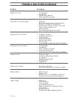
Page 42: ...correctly adjusted Engine seems to have no power Air filter clogged Plug defective Dirt in carburettor or fuel pipe Carburettor incorrectly set Choke activated or throttle wire incorrectly adjusted Engine overheats Engine overloaded Air intake or cooling flanges blocked Fan damaged Too little or no oil in engine Ignition defective Plug defective Battery does not charge One or more cells faulty Bad...

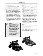
Page 43: ...in order for storage also if it is going to stand idle for more than 30 days Fuel which is left to stand for long periods 30 days or more can leave tacky deposits which can block the carburettor and interfere with the engine Fuel stabiliser is an acceptable alternative to avoid tacky deposits during storage If alkylate petrol Aspen is used stabiliser is not necessary since this fuel is stable Howe...

Page 44: ...arth 12 V negative earth Battery 12 V 24 Ah 12 V 24 Ah Spark plug Champion CJ8 or J8 Champion CJ8 or J8 electrode gap 0 7 0 8 mm electrode gap 0 7 0 8 mm Noise emissions and cutting width Measured noise level 100 dB A 100 dB A Guaranteed noise level 100 dB A 100 dB A Cutting width 850 mm 850 mm Transmission Manufacture Peerless typ MST 205 Tuff Torq K46 Oil SAE 10W 30 class SF CC No of forward gea...

Page 45: ...class SF CC Oil volume 1 4 litres 1 4 litres Start Electric starter Electric starter Noise emissions and cutting width Measured noise level 98 dB A 98 dB A Guaranteed noise level 100 dB A 100 dB A Cutting width 900 mm 900 mm Electrical system Type 12 V negative earth 12 V negative earth Battery 12 V 24 Ah 12 V 24 Ah Spark plug Champion CJ8 or J8 Champion CJ8 or J8 electrode gap 0 7 0 8 mm electrod...

Page 46: ...y 89 336 EEC and applicable supplements of May 8 2000 relating to the emission of noise to surroundings 2000 14 EC Information regarding noise emissions and the mowing width see the Technical Data The following harmonised standards have been applied EN292 2 EN836 The registered body 0404 SMP Svensk Maskinprovning AB Fyrisborgsgatan 3 SE 754 50 Uppsala Sweden has issued the report with number 01 90...

Page 47: ...6 Check and adjust tyre pressure 60 kPa 0 6 bar 7 Connect battery 8 Fill with fuel and start engine 9 Check that machine does not move in neutral Not Rider 11 10 Check Forward drive Reverse drive Operation of blades Seat safety switch Lift lever safety switch Safety switch for hydrostatic pedals neutral setting 11 Check engine revs 2 950 rpm 12 Tell customer about Need and benefits of following th...

Page 48: ...46 English SERVICEJOURNAL Work done Date mileage stamp sign ...

Page 49: ...English 47 SERVICEJOURNAL Work done Date mileage stamp sign ...

Page 50: ... H r 6C SERVICEJOURNAL Work done Date mileage stamp sign ...

Page 51: ...English 49 ...

Page 52: ... H r 6C 2002W07 114 00 48 26 ...

Reviews: