


17
MAINTENANCE
Fig. 15
Fig. 16
TRACTOR
Always observe safety rules when per form ing any
main te nance.
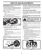
BRAKE OPERATION
If tractor requires more than five (5) feet (1,5 m) to stop at
highest speed in high est gear on a level, dry concrete or
paved surface, then brake must be checked and ad just ed.
(See “TO CHECK BRAKE” in the Ser vice and Ad just ments
section of this manual.)
TIRES
•
Maintain proper air pressure in all tires. (See the sides
of tires for proper PSI.)
• Keep tires free of gasoline, oil, or insect control
chemi cals which can harm rubber.
• Avoid stumps, stones, deep ruts, sharp objects and
other hazards that may cause tire damage.
NOTE:
To seal tire punctures and pre vent flat tires due
to slow leaks, tire sealant may be purchased from your
local parts dealer. Tire sealant also pre vents tire dry rot
and corrosion.
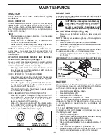
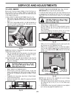
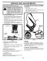
OPERATOR PRESENCE SYS TEM AND REVERSE
OPERATION SYSTEM (ROS) (See Fig. 15)
Be sure operator presence and reverse operation sys tems
are work ing properly. If your tractor does not function as
described, repair the problem immediately.
• The engine should not start unless the brake pedal is
fully de pressed, and the attachment clutch con trol is
in the dis en gaged position.
CHECK OPERATOR PRESENCE SYSTEM
•
When the engine is running, any attempt by the op er a tor
to leave the seat without first setting the parking brake
should shut off the engine.
•
When the engine is running and the at tach ment clutch
is engaged, any attempt by the operator to leave the
seat should shut off the engine.
• The attachment clutch should never operate unless
the operator is in the seat.
CHECK REVERSE OPERATION (ROS) SYSTEM
• When the engine is running with the ignition switch in
the engine "ON" position and the at tach ment clutch
engaged, any attempt by the operator to shift into
reverse should shut off the engine.
• When the engine is running with the ignition switch
in the ROS "ON" position and the at tach ment clutch
engaged, any attempt by the operator to shift into
reverse should NOT shut off the engine.
BLADE CARE
For best results mower blades must be kept sharp. Re place
bent or damaged blades.
BATTERY
Your tractor has a battery charging system which is suf fi cient
for normal use. However, periodic charging of the battery
with an automotive charger will extend its life.
• Keep battery and terminals clean.
• Keep battery bolts tight.
• Keep small vent holes open.
• Recharge at 6-10 amperes for 1 hour.
NOTE:
The original equipment battery on your tractor is
maintenance free. Do not attempt to open or remove caps
or covers. Adding or checking level of electrolyte is not
necessary.
TO CLEAN BATTERY AND TERMINALS
Corrosion and dirt on the battery and terminals can cause
the battery to “leak” power.
• Remove terminal guard.
•
Disconnect BLACK battery cable first then RED bat tery
cable and remove battery from tractor.
• Rinse the battery with plain water and dry.
•
Clean terminals and battery cable ends with wire brush
until bright.
• Coat terminals with grease or petroleum jelly.
•
Reinstall battery. (See “REPLACING BATTERY" in the
Service and Adjustments section of this manual.)
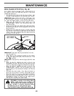
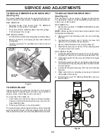
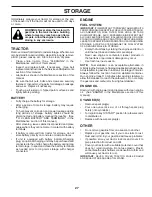
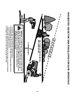
BLADE REMOVAL (See Fig. 16)
• Raise mower to highest position to allow access to
blades.
NOTE:
Protect your hands with gloves and/or wrap blade
with heavy cloth.
• Remove blade bolt by turning counterclockwise.
•
Install new or resharpened blade with stamped "GRASS
SIDE" facing the ground.
IMPORTANT:
To ensure proper assembly, center hole in
blade must align with star on mandrel assembly.
• Install and tighten blade bolt securely (45-55 Ft. Lbs./
62-75 Nm).
IMPORTANT
: SPECIAL BLADE BOLT IS HEAT TREATED.
ROS "ON"
POSITION
ENGINE "ON" POSITION
(NORMAL OPERATING)
CAUTION: Use only a replacement blade ap-
proved by the manufacturer of your tractor.
Using a blade not approved by the manu-
facturer of your tractor is hazardous, could
damage your tractor and void your warranty.
BLADE
BLADE
BOLT
(SPECIAL)
CENTER
HOLE
STAR
MANDREL
ASSEMBLY
Summary of Contents for LT19538R
Page 30: ...30 SERVICE NOTES ...
Page 32: ...06 05 2013 TH ...


