background image

6

WAR

NING

Do

no

t o

pe

rat

e m

ow

er

un

les

s c

on

tai

ne

r is

pro

pe

rly

is n

sta

lled

.Co

nta

ine

r is

su

bje

ct

to

we

ar

an

d d

eti

eri

ora

tio

n.

Ch

ec

k b

ag

fre

qu

en

tly.

Re

pla

ce

wh

en

cra

cke

d o

r d

am

ag

ed

. Us

e o

nly

a r

ec

om

me

nd

ed

rep

lac

em

en

t c

on

tai

ne

r.

WAR

NIN

G

Do

no

t o

pe

rat

e m

ow

er

un

les

s c

on

tai

ne

r is

pro

pe

rly

is n

sta

lled

.Co

nta

ine

r is

su

bje

ct

to

we

ar

an

d d

eti

eri

ora

tio

n.

Ch

ec

k b

ag

fre

qu

en

tly.

Re

pla

ce

wh

en

cra

cke

d o

r d

am

ag

ed

. Us

e o

nly

a r

ec

om

me

nd

ed

rep

lac

em

en

t c

on

tai

ne

r.

03022


CONTAINER MOUNTING (See Fig. 4)

1.   Install one container to left side fi rst with warning to 

outside of unit. Install another container to center 
position and one in right position.

NOTE: Right con tain er should always over lap left con tain er 
at  center supports.
2.      Close cover and lock latch handles over center support 

tubes.

4

FIG. 4

COVER LATCH
HANDLES

CONTAINER 
WARNING

CONTAINER 
HANDLE

CONTAINER 
WARNING

CENTER
SUPPORT
TUBES


CONTAINER ASSEMBLY (See Fig. 3)

1.    Place bottom half inside of top half, as shown.
2.   Place one foot inside bottom half and lift top half to 

meet bottom half.

3.   Press halves tightly together while lifting top to lock 

into place as shown.

IMPORTANT: BEFORE LOCKING THE TABS, HOOKED EDGES 
ON BOTH HALVES MUST OVERLAP TO FORM SEAL AS SHOWN 
IN INSET.

4.    Repeat for other containers.

PRESS TOGETHER
TO FORM SEAL
WHILE LIFTING
TOP HALF

02089

CONTAINER
BOTTOM
HALF

CONTAINER
TOP HALF

ASSEMBLY CHECK: Squeeze sides of lower half of con-
 tain er and check that there is no gap between upper and 
lower halves.  If a gap appears, unlock tabs to separate 
container halves and repeat instructions above.

LOCKING
TAB

WA

RNI

NG

Do

no

t o

pe

rat

e mo

we

r u

nle

ss

co

ntai

ner

is

prop

e

rly

iss

ub

jec

t to

we

ar

an

d d

eti

eri

ora

tio

n.

Che

ck

ba

g f

req

u

en

tly.

Re

pla

ce

wh

en

crac

ke

d o

r d

ama

ge

d.

Us

e o

nly

a r

ec

om

me

nd

ed

rep

lac

eme

nt

con

tai

ner

.

02097

FIG. 3

3

027

39

CONTAINER
BOTTOM HALF

CONTAINER
TOP HALF

Summary of Contents for GTT348

Page 1: ...021 Assembly Operation Customer Responsibilities Repair Parts 532402341 11 02 05 rad Printed in U S A OWNER S MANUAL Model GTT348 Mfg ID No 96072000900 Product No 960 72 00 09 48 Inch Mower Grass Catcher ...

Page 2: ...rcentageofridingmower relatedinjuries These operators should evaluate their ability to operate the riding mower safely enough to protect themselves and others from serious injury Followthemanufacturer srecommendationforwheelweights or counterweights Keep machine free of grass leaves or other debris build up which can touch hot exhaust engine parts and burn Do not allow the mower deck to plow leave...

Page 3: ...tion for weight limits for towed equipment and towing on slopes Never allow children or others in or on towed equipment On slopes the weight of the towed equipment may cause loss of traction and loss of control Travel slowly and allow extra distance to stop V SERVICE SAFE HANDLING OF GASOLINE To avoid personal injury or property damage use extreme care in handling gasoline Gasoline is extremely fl...

Page 4: ...g the assembly Study the operating instructions and safety precautions thoroughly to insure proper functioning of your Grass Catcher and to prevent injury to yourself and others Save this manual for future reference The operation of any tractor can result in foreign objects thrown into the eyes which can result in severe eye damage Always wear safety glasses or eye shields before starting your tra...

Page 5: ... mounting cover assembly to tractor 1 Position cover assembly on ground behind tractor 2 Liftandrotatecovertoaligncoverbracketswithsupport assembly tubes 3 Slide cover assembly down onto the support tubes FIG 2 03024 COVER ASSEMBLY SUPPORT ASSEMBLY ASSEMBLY 1 Slide flanges of support assembly into drawbar slots first then pivot backwards inserting pin into drawbar pin hole 2 Be sure support assemb...

Page 6: ...LATCH HANDLES CONTAINER WARNING CONTAINER HANDLE CONTAINER WARNING CENTER SUPPORT TUBES CONTAINER ASSEMBLY See Fig 3 1 Place bottom half inside of top half as shown 2 Place one foot inside bottom half and lift top half to meet bottom half 3 Press halves tightly together while lifting top to lock into place as shown IMPORTANT BEFORELOCKINGTHETABS HOOKEDEDGES ONBOTHHALVESMUSTOVERLAPTOFORMSEALASSHOWN...

Page 7: ...gs 6A 6B 1 Lower mower to its lowest cutting position 2 Assemble upper chute by inserting curved end into hole in back of cover NOTE Handle carefully so as not to damage full bagger indicator 3 Push in and turn upper chute until it is in line with lower chute 4 Align the bosses on lower chute with alignment slots on upper chute and slide together 5 Secure with rubber latch by hooking hole in latch...

Page 8: ...rt tubes Avoid cutting wet grass or in the morning while the dew is still heavy Grass clippings collected under these conditions tend to be sticky and adhere to the walls of the flow path causing clogging Your bagger is equipped with a full bagger indicator Movement of the wheel increases as the bags fill The wheel will be spinning fastest just before the bags fill completely When the wheel stops ...

Page 9: ...or damaged blades See BLADE CARE instructions in your tractor owner s manual CAUTION BEFOREPERFORMINGANY MAINTENANCE SERVICEORADJUST MENTS Depress clutch brake pedal fully and set parking brake Place gearshift motion control lever in NEUTRAL position Placeclutchcontrolin DISENGAGED position Turn ignition key to OFF position Make sure blades and all moving parts have completely stopped Disconnect s...

Page 10: ...r and det ieri ora tion Che ck bag freq uen tly Rep lace whe n cra cke d or dam age d Use onl y a rec om me nde d rep lace me nt con tain er 35 27 36 WAR NING Do not ope rate mo wer unl ess con tain er is pro per lyis nst alle d C ont ain er is sub ject to wea r and det ieri ora tion Che ck bag freq uen tly Rep lace whe n cra cke d or dam age d Use onl y a rec om me nde d rep lace me nt con tain e...

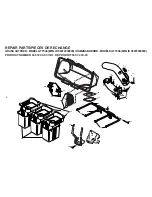
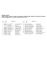
Page 11: ...130759 Rubber Latch Loquet de caoutchoc 18 532174345 Chute Lower Glissière inférieure 20 871161010 Screw 10 24 x 5 8 Vis 10 24 x 5 8 26 532124670 Spring Retainer Ressort de retenue 27 532176987 Support Assembly A Ensemble du support A 532198128 Support Assembly B Ensemble du support B 28 532165898 Spring Retainer Ressort de retenue 31 532174083 Plug Tubing End Capuchon d extrémité de tuyau 32 5321...

Reviews: