background image

 wc_tx004194gb_FM10.fm

60

General Maintenance

CRT48

5.8

Installing or Changing the Blades

Introduction

There are two types of blades available for the trowel:

Combination blades can be used throughout the entire concrete working 
process, from floating to finishing stages. They are designed for rotation in one 
direction only.

Finish blades are used only in the final stages of the concrete working process. 
While in use, these blades are pitched at progressively steeper angles to 
burnish the concrete. Finish blades are symmetrical and can be installed to 
rotate in either direction.

Requirements

Machine is stopped

Battery is disconnected to prevent unintentional start-up

Machine has been lifted via a hoist, or raised on the wheel kit.

Frame is supported on blocks while the machine is elevated. 

Combination blades or finish blades for installation

Protective gloves

Bearing grease

Procedure

Perform the procedure below to install or change the blades.

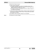
1. Remove the screws

 (a)

 from the trowel arms 

(b)

 and detach the existing blades


(c)

. Set the existing blades aside for future use or dispose of them properly if 

they have reached the end of their service life.

This procedure continues on the next page.

WARNING

Cutting hazard. Trowel blade edges are extremely sharp, especially if worn.

Always wear protective gloves when changing blades.

a

b

c

wc_gr011872

d

Summary of Contents for CRT 48-35L

Page 1: ... the enclosed manual contains Wacker Neuson references The Husqvarna Group is vouching for the quality of this product If you have any questions please do not hesitate to contact our local sales or service point or visit www husqvarnacp com Husqvarna AB SE 561 82 Huskvarna Sweden Huskvarna 2019 12 01 CRT 48 35L CRT 48 37V CRT 49 57K 1142222 26 ...

Page 2: ...Operator s Manual Ride On Trowel CRT48 37V CRT48 35L CRT48 57K Type Document Date Revision Language CRT48 37V CRT48 35L CRT48 57K 5100022491 0819 12 EN 5 1 0 0 0 2 2 4 9 1 ...

Page 3: ...m WARNING Cancer and Reproductive Harm www P65Warnings ca gov WARNING Batteries battery posts terminals and related accessories contain lead and lead compounds and other chemicals known to the State of California to cause cancer and birth defects or other reproductive harm WASH HANDS AFTER HANDLING NOTICE CALIFORNIA AIR RESOURCES BOARD CARB This machine is considered a preempt Off Road Applicatoin...

Page 4: ...CALIFORNIA Proposition 65 Warning wc_tx004643en fm 4 Notes ...

Page 5: ...he serial number in the space provided below You will need the serial number when requesting parts or service for this machine Machine documentation From this point forward in this documentation Wacker Neuson Production Americas LLC will be referred to as Wacker Neuson Keep a copy of the Operator s Manual with the machine at all times For spare parts information please see your Wacker Neuson Deale...

Page 6: ... State Health Safety Codes and Public Resources Codes specify that in certain locations spark arresters be used on internal combustion engines that use hydrocarbon fuels A spark arrester is a device designed to prevent accidental discharge of sparks or flames from the engine exhaust Spark arresters are qualified and rated by the United States Forest Service for this purpose In order to comply with...

Page 7: ...mbers dating from 2019 and onwards complies fully with the following EU directives and regulations Directive Regulation Description 2006 42 EC 2014 30 EU relating to machinery relating to electromagnetic compatibility and that the following standards and or technical specifications are applied EN 12649 2008 A1 2011 Partille 2019 12 01 Martin Huber R D Director Concrete Surfaces Floors Husqvarna AB...

Page 8: ......

Page 9: ...ifting and Transporting 32 3 1 Lifting the Machine 32 3 2 Preparing the Machine for Transport on a Truck or Trailer 33 4 Operation 35 4 1 Preparing the Machine for First Use 35 4 2 Position of the Operator 35 4 3 Machine Components 36 4 4 Machine Components Descriptions 37 4 5 Recommended Fuel Gasoline 38 4 6 Recommended Fuel Diesel 38 4 7 Refueling the Machine 39 4 8 Break In Period 40 4 9 Before...

Page 10: ...nging the Blades 60 5 9 Cleaning the Machine 62 5 10 Storage 63 5 11 Machine Disposal Decommissioning 64 6 Engine Maintenance KOHLER 65 7 Engine Maintenance Vanguard 70 8 Engine Maintenance Kubota 72 9 Troubleshooting 77 10 Technical Data 78 10 1 Engine 78 10 2 Trowel 79 10 3 Sound Measurements 80 10 4 Vibration Measurements 80 10 5 Dimensions 81 11 Emission Control Systems Information and Warrant...

Page 11: ... Neuson Emission Control Systems 90 13 AEM Safety Manual 95 14 Schematics 113 14 1 Electrical Schematic CRT48 37V 114 14 2 Electrical Schematic Components CRT48 37V 115 14 3 Fuse Relay Box Layout 115 14 4 Electrical Schematic CRT48 35L 116 14 5 Electrical Schematic Components CRT48 35L 117 14 6 Electrical Schematic CRT48 57K 118 14 7 Electrical Schematic Components CRT48 57K 119 14 8 Fuse Relay Bo...

Page 12: ...Table of Contents CRT48 wc_bo5100022491_09TOC fm 12 ...

Page 13: ...ential personal hazards Obey all safety messages that follow this symbol DANGER DANGER indicates a hazardous situation which if not avoided will result in death or serious injury To avoid death or serious injury from this type of hazard obey all safety messages that follow this signal word WARNING WARNING indicates a hazardous situation which if not avoided could result in death or serious injury ...

Page 14: ...ed under warranty The following are some examples of misuse Using the machine as a ladder support or work surface Using the machine to carry or transport passengers or equipment Using the machine to finish inappropriate materials such as slurries sealers or epoxy finishes Operating the machine outside of factory specifications Operating the machine in a manner inconsistent with all warnings found ...

Page 15: ...scription drugs Application area Be aware of the application area Keep unauthorized personnel children and pets away from the machine Remain aware of changing positions and the movement of other equipment and personnel in the application area job site Identify whether special hazards exist in the application area such as toxic gases or unstable ground conditions and take appropriate action to elim...

Page 16: ...ater wetting agents fuel gasoline diesel kerosene propane or natural gas oil coolant hydraulic oil heat transfer fluid propylene glycol with additives battery acid or grease Personal Protective Equipment PPE Wear the following personal protective equipment PPE while operating this machine Close fitting work clothes that do not hinder movement Safety glasses with side shields Hearing protection Saf...

Page 17: ...a qualified technician Turn off the machine before performing maintenance or making repairs Remain aware of the machine s moving parts Keep hands feet and loose clothing away from the machine s moving parts Reinstall the safety devices and guards after repair and maintenance procedures are complete Machine modifications When servicing or maintaining the machine Use only accessories attachments tha...

Page 18: ...explosive Personal protective equipment PPE Wear the following Personal Protective Equipment PPE while servicing or maintaining this machine Close fitting work clothes that do not hinder movement Safety glasses with side shields Hearing protection Safety toed footwear In addition before servicing or maintaining the machine Tie back long hair Remove all jewelry including rings ...

Page 19: ...ling the engine Clean up any spilled fuel immediately Refill the fuel tank in a well ventilated area Reinstall the fuel tank cap after refueling Do not smoke Do not refuel a hot or running engine Do not refuel the engine near sparks or open flames Use suitable tools for refueling for example a fuel hose or a funnel Do not refuel if the machine is positioned in a truck fitted with a plastic bed lin...

Page 20: ...r hold the machine safely See the Technical Data chapter for machine weight Remain aware of the location of other people when lifting the machine Only use the lifting points and tie downs described in the Operator s Manual Make sure the transporting vehicle has sufficient load capacity and platform size to safely transport the machine To reduce the possibility of injury Do not stand under the mach...

Page 21: ...wc_si000969gb_FM10 fm 21 CRT48 Safety Information Notes ...

Page 22: ...wc_si000970gb_FM10 fm 20 Labels CRT48 2 Labels 2 1 Label Locations wc_gr013222 A B G L P U K AA H EE C D E Q R S T M F Q K P L L Z Z X G FF G G Z Z N L F Y DD W J CC V BB GG HH ...

Page 23: ...perator s Manual No sparks flames or burning objects near the machine Stop the engine before refueling B Water tank fill Use only clean water or water based retardants C WARNING Always wear hearing and eye protection when operating this machine STOP STOP 0178751 173440 173440 STOP STOP DIESEL DIESEL DANGER DANGER PELIGRO PELIGRO DANGER DANGER 178752 178752 STOP STOP 178745 178745 WARNING WARNING A...

Page 24: ...TRES A DES BLESSURES LEA Y ENTIENDA EL MANUAL DE OPERACION PROVISTO CON EL EQUIPO ANTES DE QUE OPERE ESTE EQUIPO LEA Y ENTIENDA EL MANUAL DE OPERACION PROVISTO CON EL EQUIPO ANTES DE QUE OPERE ESTE EQUIPO DE NO HACERSE ASI PODRIA AUMENTAR EL RIESGO DE LOS DAÑOS PERSONALES Y A OTRAS PERSONAS DE NO HACERSE ASI PODRIA AUMENTAR EL RIESGO DE LOS DAÑOS PERSONALES Y A OTRAS PERSONAS READ AND UNDERSTAND T...

Page 25: ... AVERTISSEMENT AVERTISSEMENT WARNING WARNING 178713 178713 WARNUNG WARNUNG ADVERTENCIA ADVERTENCIA WARNING WARNING AVERTISSEMENT AVERTISSEMENT 117037 117037 178732 178732 WARNING WARNING 5200007832 5200007832 AVERTISSEMENT AVERTISSEMENT ADVERTENCIA ADVERTENCIA WARNUNG WARNUNG 5200007834 5200007834 111453 111453 AVERTISSEMENT AVERTISSEMENT ADVERTENCIA ADVERTENCIA WARNING WARNING ...

Page 26: ...G Hand injury if caught in moving belt Always replace beltguard K NOTICE Lifting point L Tie down point M Key switch engine start Off On Start 110164 110164 ADVERTENCIA ADVERTENCIA AVERTISSEMENT AVERTISSEMENT WARNING WARNING 178711 5200014673 5200014673 XXX kg XXX kg XXXX LBS XXXX LBS 118084 118084 ...

Page 27: ...LUS PROCHE POUR COMMANDER UN EXEMPLAIRE SUPPLEMENTAIRE POUR COMMANDER UN EXEMPLAIRE SUPPLEMENTAIRE EL MANUAL DE OPERACION DEBE SER RETENIDO EN LA EL MANUAL DE OPERACION DEBE SER RETENIDO EN LA MAQUINA CONTACTE A SU DISTRIBUIDOR WACKER MAS MAQUINA CONTACTE A SU DISTRIBUIDOR WACKER MAS CERCANO PARA PEDIR UN EJEMPLAR ADICIONAL CERCANO PARA PEDIR UN EJEMPLAR ADICIONAL OPERATOR S MANUAL MUST BE STORED ...

Page 28: ...RNING Entanglement hazard Rotating machinery V Use only Glygoyle 460 gear oil in gearbox W This machine may be covered by one or more patents 164909 164909 165016 165016 178717 178717 AVERTISSEMENT AVERTISSEMENT 154657 154657 ADVERTENCIA ADVERTENCIA WARNING WARNING USE USE ONLY ONLY MOBIL MOBIL GLYGOYLE 460 GLYGOYLE 460 WACKER NEUSON WACKER NEUSON P N 163918 P N 163918 www wackerneuson com www wac...

Page 29: ...IRECCION SERVO ASISTIDA ESTA BAJO CARGA VEA EL MANUAL ESTA BAJO CARGA VEA EL MANUAL DE OPERACION PARA EL SERVICIO DE OPERACION PARA EL SERVICIO ATTENTION ATTENTION DIE SERVOLENKUNG IST UNTER DIE SERVOLENKUNG IST UNTER LAST WARTUNGSINFORMATION LAST WARTUNGSINFORMATION IST IN DER BETRIEBSANLEITUNG IST IN DER BETRIEBSANLEITUNG ZU FINDEN ZU FINDEN STEERING ASSIST SYSTEM UNDER STEERING ASSIST SYSTEM UN...

Page 30: ...hich can cause engine damage personal injury or death Read and follow the engine starting instructions in this Operator s Manual if equipped EE Caution Check engine if equipped 5200007831 5200007831 WARNUNG WARNUNG QUETSCH ZONE VERMEIDEN QUETSCH ZONE VERMEIDEN EVITE ZONA DE APRIETE EVITE ZONA DE APRIETE ADVERTENCIA ADVERTENCIA AVERTISSEMENT AVERTISSEMENT EVITER ZONE DE RACCORDEMENT A PINCE EVITER ...

Page 31: ...65Warnings ca gov WARNING AVERTISSEMENT ADVERTENCIA 5100045462 1 1 8 6 8 8 R e m v e p n f r m t r w e l b e f r e l i f t i n g m c h i n e v e r h e d P n s c n f l l n d c u s e d e t h r s e r i u s i n j u r y i f p e r s n i s h i t G l e i t s c h e i b e v m B e t n g l ä t t e r e n t f e r n e n b e v r d s G e r ä t u b e r K p f h ö h e g e h b e n w i r d G l e i t s c h e i b e k n n...

Page 32: ...he machine Perform the procedure below to lift the machine 1 Attach a sling or chain through the lifting tubes or use a fork lift Do not attach lifting devices to any other part of the machine 2 Lift the machine a small distance 3 Check for stability If necessary lower the machine reposition the lifting devices and lift the machine a small distance again 4 Continue lifting the machine only when it...

Page 33: ...e material If the machine is mounted to a trailer do not use the machine s trailer jack to support the trailer tongue during transporting Check that any ramps used in the loading process Can support the weight of the machine Are clean and free of grease oil ice and other loose material Are securely connected to the transport vehicle or trailer Are of sufficient length to keep the loading angle 15 ...

Page 34: ...wc_tx004192gb_FM10 fm 34 Lifting and Transporting CRT48 Note Graphic is representative only Your machine may vary wc_gr011880 ...

Page 35: ...ng location 6 Connect component parts not already attached 4 2 Position of the Operator Safe and efficient use of this machine is the operator s responsibility Full control of the machine is not possible unless the operator maintains the proper working position at all times While operating this machine the operator must be seated in the operator s seat facing forward have both feet on the control ...

Page 36: ...wc_tx004193gb_FM10 fm 36 Operation CRT48 4 3 Machine Components wc_gr013209 a b d e f g h j k m n o u t q r s c p ...

Page 37: ...ers c and how to start the machine 2 Have the operator practice steering the trowel A hard concrete slab slightly wetted with water is an ideal surface on which to practice 3 Pitch the blades up approximately 6 35 mm on the leading edge Start by making the machine hover in one spot and then practice moving the machine in a straight line and making 180 turns The best control is achieved at full rpm...

Page 38: ...ume You may use gasoline containing up to 10 ethanol by volume commonly referred to as E10 Gasoline containing more than 10 ethanol such as E15 E20 or E85 may not be used because it could damage the engine If you notice any undesirable operating symptoms try another service station or switch to another brand of gasoline Fuel system damage or performance problems resulting from the use of an oxygen...

Page 39: ...e for proper operation of the venting port c 3 Re install the fuel cap Result The machine has now been refueled WARNING Fire and burn hazard Fuel and its vapors are extremely flammable Keep all sources of ignition away from the machine while refueling Refuel only when the machine is outdoors Clean up spilled fuel immediately wc_gr013207 a c b CAUTION Fire and health hazard Fuel expands when heated...

Page 40: ...machine in cold weather Vanguard engine break in period Follow the recommendations below while operating the machine during the break in period Do not operate at full load during the first 5 10 hours of operation Change the oil after the first 5 10 hours of operation Allow the machine to warm up completely before operating the machine in cold weather Kubotaengine break in period Follow the recomme...

Page 41: ...he machine 1 Sit in the operator s seat 2 Turn the starting key a clockwise until the engine starts NOTICE Cranking the engine for more than five seconds can cause starter damage If the engine fails to start release the key switch and wait 10 seconds before operating the starter again If the engine still will not start after multiple attempts see chapter Troubleshooting 3 Press the throttle pedal ...

Page 42: ... area while giving the operator an excellent view of the slab surface to be troweled When the machine reaches the end of the slab make a 180 U turn and repeat the straight line of direction to the other end of the slab Alternatively move the machine laterally sideways and then travel backward to the other end of the slab Remember that the best possible control is achieved at maximum engine speed N...

Page 43: ...ion 3 When the glow plug indicator light b turns off turn the key switch to the START position and hold until the engine starts NOTICE Cranking the engine for more than five seconds can cause starter damage If the engine fails to start release the key switch and wait 10 seconds before operating the starter again If the engine still will not start after multiple attempts see chapter Troubleshooting...

Page 44: ... area while giving the operator an excellent view of the slab surface to be troweled When the machine reaches the end of the slab make a 180 U turn and repeat the straight line of direction to the other end of the slab Alternatively move the machine laterally sideways and then travel backward to the other end of the slab Remember that the best possible control is achieved at maximum engine speed N...

Page 45: ... Turn the starting key a clockwise to the crank position until the engine starts NOTICE Cranking the engine for more than five seconds can cause starter damage If the engine fails to start release the key switch and wait 10 seconds before operating the starter again If the engine still will not start after multiple attempts see chapter Troubleshooting 3 Allow the engine to warm up before operating...

Page 46: ...e in the direction that the operator is facing This will finish the widest possible area while giving the operator an excellent view of the slab surface to be troweled When the machine reaches the end of the slab make a 180 U turn and repeat the straight line of direction to the other end of the slab Alternatively move the machine laterally sideways and then travel backward to the other end of the...

Page 47: ...the machine 2 Set the desired pitch on the left side of the machine To increase the pitch turn the pitch control inward a 3 Adjust the right side to match 4 Use the pitch indicator b to adjust pitch equally on both right and left trowel blades Suggested working pitch wc_gr013211 a b 5 10º 15º 20 25º Working conditions of concrete Suggested working pitch 1 Wet surface working stage Flat no pitch 2 ...

Page 48: ...own or accident occurs while the machine is operating follow the procedure below 1 Stop the engine 2 Close the fuel valve 3 Remove the machine from the job site using the wheel kit 4 Clean concrete from the blades and the machine 5 Contact the rental yard or machine owner for further instructions ...

Page 49: ...repairs must be performed by a dealer service center authorized by Wacker Neuson The use of service parts that are not equivalent in performance and durability to authorized parts may impair the effectiveness of the emission control system and may have a bearing on the outcome of a warranty claim WARNING A poorly maintained machine can malfunction causing injuries or permanent damage to the machin...

Page 50: ...signated with square bullet points require special training and equipment Daily Every 20 hours Every 50 hours Every 300 hours Lubricate trowel arms Check external hardware Pressure wash all surfaces until free of concrete Check oil level in gearboxes Lubricate gearbox input shaft fitting Lubricate drive and pitch controls Check drive belt for wear Lubricate steering cylinder pivots Replace oil in ...

Page 51: ... oil fill plugs b Remove one gearbox oil fill plug 2 If the level is below the threads of the oil fill plug hole add synthetic gear oil through the opening Do not overfill 3 Wipe the threads dry on both the gearbox and the oil fill plug 4 Apply Loctite 545 or equivalent to the oil fill plug threads replace the oil fill plug and torque to 16 20 Nm 12 15 ft lbs NOTICE Do not mix types of gear oil Do...

Page 52: ...the back of the trowel upwards to allow the remaining oil to drain 4 After all the oil has drained wipe the threads dry on both the gearbox and the oil drain plug 5 Apply Loctite 545 or equivalent to the oil drain plug threads and replace the gearbox oil drain plug 6 With the trowel level fill the gearbox with approximately 1 83 L 62 oz synthetic gear oil through the oil fill plug as described abo...

Page 53: ...ocedure Perform the procedure below to adjust the blade arms 1 Using an appropriate hoist or crane raise the machine off the ground so that the blades at full pitch will not touch the ground 2 Set the machine on four jack stands a as shown below 3 Using the pitch controls b adjust the blades so that they are between 1 2 and full pitch approximately 12 4 Disconnect the battery This procedure contin...

Page 54: ... machine frame Measure the distance x between the machine frame at the reference mark and the bottom edge of the blade Rotate the blades as necessary to measure the distance x for each blade Note Rotate the blades by manually turning the drive belt 6 Determine the average distance x Adjust any blade that does not measure the distance x 1 25 mm 0 050 in To adjust Loosen or tighten the pitch links d...

Page 55: ...ease the trowel arms 1 Set the trowel on a flat level surface 2 Disconnect the battery 3 For access pitch the blades to the maximum angle 4 Apply grease to each zerk a on the spider assembly 5 Apply grease to the lifting ring b on each side of the machine Note Graphic is representative only Your machine may vary Result The trowel arms have now been greased wc_gr011908 a wc_gr011909 b ...

Page 56: ...weight bearing capacity to lift the machine Properly rated jack stands Mounting a 48 float pan Perform the procedure below to mount a 48 float pan 1 Stop the engine 2 Using an appropriate hoist or crane raise the machine off the ground so that the blades will not touch the ground 3 Set the machine on jack stands a as shown below Note Graphic is representative only Your machine may vary 4 Position ...

Page 57: ...6 float pan 1 Loosen and remove the bolts d that attach each blade e 2 Move the blades inward to align with mounting holes f 3 Re install and tighten the bolts in mounting holes 4 Attach the 46 pan to the blades WARNING Float pans can fall off a raised trowel striking nearby personnel Do not lift the trowel overhead after float pans have been mounted wc_gr011866 f d e ...

Page 58: ...rm the procedure below to replace the drive belt 1 Set the trowel on a flat level surface with the blades pitched flat 2 Disconnect the battery 3 Remove the beltguard a Note Graphic is representative only Your machine may vary 4 Remove the three bolts b holding the universal joint to the drive pulley 5 Loosen the pillow block bearing c 6 Remove the old drive belt d 7 Install a new drive belt a b c...

Page 59: ...mble the belt drive 1 Align the pillow bearing and shaft as straight as possible Adjust pulley offset and center distance to values as shown 2 Re install the three bolts and torque to 14 1 4 Nm 10 1 ft lbs 3 Re install the beltguard 4 Reconnect the battery Result The drive belt has now been replaced ...

Page 60: ...rection Requirements Machine is stopped Battery is disconnected to prevent unintentional start up Machine has been lifted via a hoist or raised on the wheel kit Frame is supported on blocks while the machine is elevated Combination blades or finish blades for installation Protective gloves Bearing grease Procedure Perform the procedure below to install or change the blades 1 Remove the screws a fr...

Page 61: ...of each blade correctly for the rotation of each rotor If installing finish blades simply align the screw holes Blade orientation is not critical with finish blades 3 Coat the screw threads with bearing grease A grease coating will prevent wet concrete from cementing the screws in place This step will also make blade removal easier in the future 4 Re install the screws and tighten securely Do not ...

Page 62: ... the machine 1 Use a pressure washer to remove concrete and debris from the trowel blades wheels and ring guards 2 Keeping a minimum distance of 1 meter 3 feet away use the pressure washer to rinse the trowel body NOTICE Direct high water pressure at close range will damage certain components on the machine The following components should be wiped clean by hand using a damp clean cloth Do not appl...

Page 63: ... After completing the procedures listed above fill the fuel tank completely and add a high quality stabilizer to the fuel Choose a stabilizer that includes cleaning agents and additives designed to coat protect the cylinder walls Make sure the stabilizer you use is compatible with the fuel in your area fuel type grade and temperature range Do not add extra alcohol to fuels which already contain it...

Page 64: ...nvironmental regulations pertaining to the disposal of construction equipment Preparation Perform the following tasks to prepare the machine for disposal Move the machine to a protected location where it will not pose any safety hazards and cannot be accessed by unauthorized individuals Ensure that the machine cannot be operated from the time of final shutdown to disposal Drain all fluids includin...

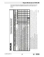
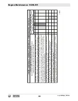
Page 65: ...machine Use an engine oil of appropriate viscosity based on the expected outside air temperature See the table below WARNING Most used liquids from this machine such as oil gasoline grease etc contain small amounts of materials that can cause cancer and other health problems if inhaled ingested or left in contact with skin for prolonged periods of time Take steps to avoid inhaling or ingesting use...

Page 66: ...se Semi Sintetica Base Semi Synthétique Halbsynthetische Basis Base Semi Sintetica Base Semi Sintética Synthetic Base Base Sintetica Base Synthétique Synthetische Basis Base Sintetica Base Sintética F C SAE Viscosity Grade Gradazioni SAE Viscosité SAE SAE Viskositätsklasse Viscosidad SAE Gradação SAE OIL CLASSIFICATIONS API MIL SEQUENZE API MIL SEQUENCES API MIL API MIL SEQUENZEN SECUENCIAS API MI...

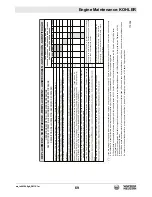
Page 67: ...tre à Air à Panneau à Sec Remote Air Filter Dry Type Filtro Aria a Distanza a Secco Filtre à Air à Distance à Sec Combustíveis Fan Alternator Belt Tension Tensione Cinghia Ventola Alternatore Tension Courroie Ventilateur Alternateur Keilriemens Lüfter Tensión Correa Ventilador Alternador Tensão Cincha Ventilador Alternador CHECK CONTROLLO CONTRô LE KONTROLLE COMPROBACìON CONTRô LE ORDINARY MAINTEN...

Page 68: ...arance Registro Gioco Valvole Réglage Jeu Soupapes Einstallen des Ventilspiels Ajuste da Tolarância Registro Juego de Válvulas Apuramento válvula Injector Cleaning and Adjustment Taratura e Pulizia Iniettori Tarage et Nettoyage Injecteur Einspritzdüsen Überprüfen Ajuste y Limpieza Inyectores Taradura e Limpeza Injectores Flush Radiator Pulizia Interna Radiatore Nettoyage Intérieur du Radiateur Inn...

Page 69: ...ir Filter Massa Filtrante Filtro Aria a Pannello Masse Filtrante de Filtre à Air á Panneau 10 250 300 500 1000 5000 10000 If you are using oil of a quality lower than the prescribed one then you will have to replace it every 125 hours for the standard sump and every 150 hours for the enhanced sump Se si utilizza olio di qualità inferiore a quello prescritto sostituirlo ogni 125 ore per la coppa st...

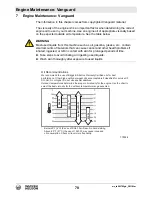
Page 70: ...or left in contact with skin for prolonged periods of time Take steps to avoid inhaling or ingesting used liquids Wash skin thoroughly after exposure to used liquids Oil Recommendations We recommend the use of Briggs Stratton Warranty Certified oils for best performance Other high quality detergent oils are acceptable if classified for service SF SG SH SJ or higher Do not use special additives Out...

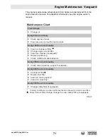
Page 71: ...rs or Annually Clean or change air filter Change engine oil and filter Clean pre cleaner if equipped Replace spark plug Check muffler and spark arrester Every 250 Hours or Annually Check valve clearance Adjust if necessary Every 400 Hours or Annually Change air filter Replace fuel filter Clean air cooling system Clean oil cooler fins Every 600 Hours or Annually Change safety filter if equipped In ...

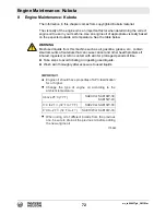
Page 72: ...mall amounts of materials that can cause cancer and other health problems if inhaled ingested or left in contact with skin for prolonged periods of time Take steps to avoid inhaling or ingesting used liquids Wash skin thoroughly after exposure to used liquids Engine oil should have properties of API classification SL or higher Change the type of engine oil according to the ambient temperature When...

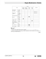
Page 73: ...ble below The schedule applies to an engine in use under normal conditions 2 If you do not have the proper tools and or are not mechanically proficient contact your local KUBOTA dealer Items Interval Remarks Every 8 hours daily Every 50 hours Every weekly 100 hours Every 200 hours Each part Check Clean To ensure the best quality and reliability use new KUBOTA Genuine parts or their equivalents for...

Page 74: ...e oil Check Replenish Change To ensure the best quality and reliability use new KUBOTA Genuine parts or their equivalents for repair and replacement whenever you have maintenance done Change Clean Spark plug Oil filter cartridge Adjust Change Check Clean Air cleaner element Change 1 clamp bands Intake pipe Change Fuel filter Check Change Clean Fuel tank Gasoline line Check setting LPG line Fuel pi...

Page 75: ...00 hours Every 200 hours Change Breather tube PCV valve To ensure the best quality and reliability use new KUBOTA Genuine parts or their equivalents for repair and replacement whenever you have maintenance done Check LPG vaporizer Check regulator Hot water line Change Hot water line Check inner parts 2 LPG Lock off valve Check Check Battery Change Check Change Radiator coolant Radiator hoses Check...

Page 76: ... Yearly years Change Breather tube PCV valve Check To ensure the best quality and reliability use new KUBOTA Genuine parts or their equivalents for repair and replacement whenever you have maintenance done LPG vaporizer Check regulator Hot water line Change Hot water line Check inner parts 2 LPG Lock off valve Check Check Battery Change Check Change Radiator coolant Radiator hoses Check Change and...

Page 77: ...rcuit failure Check fuel lines Machine out of balance wobbling excessively Trowel arm s bent Replace trowel arm s Trowel arm s out of adjustment Adjust trowel arm s Trowel blade s bent Replace trowel blade s Poor handling excessive free play in steering mechanism Worn pivot bearings rod ends and or cylinder mounts Inspect pivot bearings rod ends and cylinder mounts Replace as needed Machine does n...

Page 78: ...del A C V Twin KDW1404 WG1605 G Maximum rated power rated speed kW hp 27 6 37 3600 rpm1 26 34 9 3600 rpm2 42 5 57 3600 rpm1 Displacement cm in 993 61 1372 84 1537 93 8 Operating speed rpm 4000 3600 Engine speed idle rpm 1200 1450 1000 Battery V size 12 BCI G24 Fuel type Regular unleaded gasoline Diesel Regular unleaded gasoline Fuel tank capacity L gal 24 6 6 5 Fuel consumption L gal hr 10 2 75 6 ...

Page 79: ... x 58 Rotor speed range rpm 25 165 25 150 Blade pitch range degrees 0 25 Gearbox type Heavy duty fan cooled Gearbox lubrication type L oz Mobil Glygoyle 460 1 83 62 each Driveshaft type Splined universal joint Operation Troweling width with pans non overlapping without pans non overlapping mm in 2465 97 2413 95 Troweling area with pans non overlapping without pans non overlapping m2 ft2 3 32 2 8 3...

Page 80: ...tested for hand arm vibration HAV level and whole body vibration in accordance with ISO 5349 EN 1033 and ISO 2631 where applicable Vibration uncertainties Hand transmitted vibration was measured per ISO 5349 1 This measurement includes an uncertainty of 1 5 m s2 Whole body vibration was measured per ISO 2631 1 This measurement includes an uncertainty of 0 3 m s2 Machine Sound Pressure at Operator ...

Page 81: ...wc_td000668gb_FM10 fm 81 CRT48 Technical Data 10 5 Dimensions mm in 2566 101 1473 58 1295 51 wc_gr013206 ...

Page 82: ...wc_td000668gb_FM10 fm 82 Technical Data CRT48 Notes ...

Page 83: ...Emissions The combustion process produces carbon monoxide oxides of nitrogen and hydrocarbons Control of hydrocarbons and oxides of nitrogen is very important because under certain conditions they react to form photochemical smog when subjected to sunlight Carbon monoxide does not react in the same way but it is toxic Problems that may affect Emissions If any of the following symptoms arise have t...

Page 84: ... engine equipment assure yourself that such part is warranted by its manufacturer to be equivalent to the parts offered by Wacker Neuson in performance and durability Furthermore if such a replacement part is used in the repair or maintenance of the engine equipment and an authorized Wacker Neuson dealer service center determines it is defective or causes a failure of a warranted part the claim fo...

Page 85: ... manual Wacker Neuson recommends that all receipts covering maintenance on the engine equipment be retained but Wacker Neuson cannot deny warranty coverage solely for the lack of receipts or for the failure to ensure the performance of all scheduled maintenance Normal maintenance replacement or repair of emission control devices and systems may be performed by any repair establishment or individua...

Page 86: ... must take your Wacker Neuson engine equipment along with proof of original purchase date at your expense to the authorized Wacker Neuson dealer service center during their normal business hours For owners located more than 100 miles from an authorized dealer service center excluding the states with high altitude areas as identified in 40 CFR Part 1068 Appendix III Wacker Neuson will pay for pre a...

Page 87: ...ems Information and Warranty 11 Emissions Control Systems Information and Warranty System Covered Components Air filter system and associated plumbing Before engine intake Air filter Exhaust system Exhaust system connected after the exhaust manifold ...

Page 88: ...Neuson Emission Control Systems The warranty period for this engine equipment begins on the date of sale to the initial purchaser and continues for a period of 5 years or 3000 hours of operation whichever comes first For the warranty terms for your specific engine equipment visit wackerneuson com Any implied warranties are limited to the duration of this written warranty ...

Page 89: ...purchase Exhaust Emissions The combustion process produces carbon monoxide oxides of nitrogen and hydrocarbons Control of hydrocarbons and oxides of nitrogen is very important because under certain conditions they react to form photochemical smog when subjected to sunlight Carbon monoxide does not react in the same way but it is toxic Wacker Neuson utilizes lean carburetor settings and other syste...

Page 90: ... is also liable for damages to other engine equipment components caused by a failure of any warranted parts during the warranty period What is covered Wacker Neuson recommends the use of genuine Wacker Neuson parts or the equivalent whenever maintenance is performed The use of replacement parts not equivalent to the original parts may impair the effectiveness of the engine equipment emission contr...

Page 91: ...tenance on the engine equipment be retained but Wacker Neuson cannot deny warranty coverage solely for the lack of receipts or for the failure to ensure the performance of all scheduled maintenance Normal maintenance replacement or repair of emission control devices and systems may be performed by any repair establishment or individual however warranty repairs must be performed by an authorized Wa...

Page 92: ... in 40 CFR Part 1068 Appendix III Wacker Neuson will pay for pre approved shipping costs to and from an authorized Wacker Neuson dealer service center Claims for repair or adjustment found to be caused solely by defects in material or workmanship will not be denied because the engine equipment was not properly maintained and used The warranty repairs should be completed in a reasonable amount of t...

Page 93: ...ust emission warranty statement See the supplied engine owner s manual for the applicable exhaust emission warranty statement CRT48 37V System Covered Components Evaporative control system Fuel tank Fuel cap Fuel line Fuel vent fitting CRT48 57K System Covered Components Exhaust system Pipe engine Catalytic converter Evaporative control system Fuel tank Fuel cap Fuel line Fuel return fitting ...

Page 94: ...Neuson Emission Control Systems The warranty period for this engine equipment begins on the date of sale to the initial purchaser and continues for a period of 3 years or 2500 hours of operation whichever comes first For the warranty terms for your specific engine equipment visit wackerneuson com Any implied warranties are limited to the duration of this written warranty ...

Page 95: ...t We wish to thank the members of the Association of Equipment Manufacturers for their invaluable contributions in preparing this Safety Manual NOTICE OF COPYRIGHT PROTECTION Copyright 2017 by the Association of Equipment Manufacturers All rights reserved This work may not be reproduced or disseminated in whole or in part by any means without the prior written permission of the Association of Equi...

Page 96: ...irectly from the manufacturer Keep this safety manual and the manufacturer s manual s with the machine at all times Read and understand all manuals Safety videos and other training resources are available from some manufacturers and dealers Operators are encouraged to periodically review these resources Read and understand manuals before operating 3 Foreword Safety Alert Symbol This Safety Alert S...

Page 97: ...lied by the manufacturer be trained including actual operation and know the safety rules and regulations for the job site It is a good safety practice to point out and explain safety signs and practices to others and to make sure they understand the importance of following these instructions WARNING Death or serious injury could result from operating machinery while impaired by drugs or alcohol Dr...

Page 98: ...pected to obey OSHA enforces federal laws within the United States that apply to the safe operation application and maintenance of equipment on some job sites It is the employer s responsibility to comply with these laws A federal representative may periodically inspect a job site to see that these laws are being followed There may be other local state provincial federal laws or international orga...

Page 99: ...tem and wear approved personal safety equipment such as a dust particle respirator designed to filter out microscopic particles Read and understand manuals before operating Follow a Safety Program 9 Load and Unload Safely Precautions Power trowels are heavy and awkward to move around Do not attempt to lift the ride on trowel by the guard rings Use proper heavy lifting procedures Keep all non essen...

Page 100: ...if damaged or missing Ensure all tools or loose objects are removed or securely fastened before operating the machine Inspect the machine before each work day Prepare for Safe Operation 11 Hydraulic Fluid Injection Hazard WARNING Accidental injection of pressurized fluid into the hands or body is dangerous and could result in death or serious injury Use caution when checking hydraulic leaks as pre...

Page 101: ... done No smoking and no open flames in flammable explosive atmospheres Allow radiator to cool before removing cap slowly Prepare for Safe Operation 13 Ultra Low Sulfur Diesel ULSD Fuel Hazard Avoid Static Electricity Risk When Fueling WARNING Ultra Low Sulfur Diesel ULSD poses a greater static ignition hazard than earlier diesel formulations Avoid death or serious injury from fire or explosion consu...

Page 102: ... the worksite shower and change into clean clothing before leaving the worksite 8 Do not eat drink use tobacco products or apply cosmetics in areas where there is dust containing crystalline silica 9 Store food drink and personal belongings away from the work area 10 Wash hands and face before eating drinking smok ing or applying cosmetics after leaving the exposure area Avoid silica dust Prepare ...

Page 103: ...machine make sure that a circular area with a minimum radius equal to the length of the machine is clear This will ensure safety of personnel around the machine Before starting walk completely around trowel Start Safely 17 Starting Aids If you have trouble starting the engine and need to use jumper cables follow the instructions in manufacturer s operating manual s Jump starting is a two person op...

Page 104: ...s are free of obstructions and the area is clear for operation Start the trowel following the instructions in the engine manufacturer s operation manual For diesel powered trowels follow the instructions for glow plug and cold start operation Observe any gauges and warning lights to ensure they are functioning and their readings are within the manufacturer s normal operating range Check operation ...

Page 105: ...hazardous unless performed properly Be sure you have the necessary skill information correct tools and proper equipment to do the job safely Be sure to maintain the equipment according to the manufacturer s instructions Regularly check the operation of the protective and safety devices Do not perform any work on a machine unless you are authorized and qualified to do so If you have been authorized...

Page 106: ...ion and clearance Remove oil grease or water to eliminate any slippery surfaces Clean around the area to be serviced to minimize contamination Prepare the Machine Stored energy sources electrical mechanical hydraulic pneumatic chemical thermal etc must be controlled or reduced to a practical minimum before performing any maintenance repair or service procedures CAUTION Load and unload machinery us...

Page 107: ...eplace blades and pans as a complete set even if only one blade or pan is showing wear or damage They can wear differently depending on different jobs and a difference in blade size will damage the finish of the slab surface Only use manufacturer approved polishing and brush attachments WARNING Avoid rotating parts 25 Perform Maintenance Safely 25 Common Maintenance Safety Practices Use Proper Ven...

Page 108: ...ly 27 Perform Maintenance Safely 27 Hydraulic System Hazards cont During inspection of the hydraulic system Wait for fluid to cool before disconnecting the lines Hot hydraulic fluid can cause severe burns Wear appropriate eye protection Hydraulic fluid can cause permanent eye injury When venting or filling the hydraulic system loosen the filler cap slowly and remove it gradually Never reset any re...

Page 109: ...harged Keep arcs sparks flames and lighted tobacco away Do not smoke near batteries Keep them away from arcs sparks and open flames Provide adequate ventilation Never check the battery by placing a metal object across the battery posts The resulting spark could cause an explosion WARNING Avoid serious injury from battery explosion Do not charge a battery or jump start the engine if the battery is f...

Page 110: ...tioning properly Test the machine if necessary After testing shut down and check the work you performed Recheck all fluid levels before releasing the equipment for operation All parts should be inspected during repair and replaced if worn cracked or damaged Excessively worn or damaged parts could fail and cause injury or death Install all guards covers and shields after servicing Refill and rechar...

Page 111: ...33 Notes 34 Notes ...

Page 112: ...will help to build good judgment in all situations Our objective is to help you develop establish and maintain good safety habits to make operating a concrete power trowel easier and safer for you Final Word to the User Many pictorials in this safety manual can be downloaded at http pictorials aem org For additional publications visit our website at www safetymaterials org This manual is one in a ...

Page 113: ...CRT48 Schematics wc_tx004197gb_FM10 fm 113 14 Schematics Notes ...

Page 114: ...ER GRND KEY SWITCH 6 BR 13 WH 3 BR 23 BU 63 RD 4 BR 24 BU 7 BR 14 WH LIGHT RT REAR LIGHT RT FRONT OPERATOR THROTTLE POWER STEER OPERATOR SEAT B A B A B A 11 BR 10 BR 42 BR 8 BR 48 RD 15 WH 16 WH LIGHT LT FRONT LIGHT LT REAR OIL COOLER GRND TO FRAME B A B A B A SP 7 13 WH 15 WH 16 WH 14 WH 17 WH 17 WH 38 RD 39 RD 37 PU SPRAY SWITCH LIGHT SWITCH 33 PK 37 PU 12 BR 32 RD 40 RD 9 BR 28 BK 35 BR 6 5 4 3...

Page 115: ...0 Battery positive 10 Light RT front 21 Fuse relay 11 Light RT rear Wire Colors BLK Black RED Red WHT White ORG Orange GRN Green TAN Tan YEL Yellow BRN Brown BLU Blue VIO Violet GRY Gray PNK Pink Position Description A Key 20 amp B Lights 15 amp C Water pump E Oil cooler F Power steer harness G Spare 15 H Spare 5 J Auxiliary relay L Oil cooler relay M Operator presence relay 4 4 3 2 1 A B C 5 8 12...

Page 116: ... 22 BRN 7 RED 39 PNK 34 PRPL 36 OIL PRESSURE LIGHT YEL 43 ALTERNATOR LIGHT ORG 44 COOLANT TEMP LIGHT RED 42 WORK LIGHTS 12V PNK 16 LIGHT SWITCH OUTPUT COOLANT TEMP LIGHT ALTERNATOR LIGHT OIL PRESSURE LIGHT PNK 18 PNK 17 BRN 9 PACKARD WEATHERPACK PACKARD WEATHERPACK BRN 10 PNK 47 RED 3 ORG 44 CAV 1 BLU 41 CAV 2 BRN 6 PNK 40 PNK 37 87 PNK 51 JUMPER 87 BLU 24 85 PNK 32 350mm 30 BLK 27 WHT 38 BRN 5 BL...

Page 117: ...y system 6 Throttle sense switch normally closed 21 Voltage regulator 7 Right front light 22 Alternator 8 Right rear light 23 Glow plug temperature sensors 9 Left rear light 24 Glow plugs 10 Left front light 25 Keyed power fuse 11 Fuse spray system 26 Glow plug relay 12 Fuse light circuit 27 12V to Power Steer Circuit 13 Light switch 28 Alternator light 14 Spray pump switch 29 Coolant temperature ...

Page 118: ...tx004197gb_FM10 fm 14 6 Electrical Schematic CRT48 57K Note The machine may or may not have Item 32 and the Alt B connection 1 2 3 4 5 6 7 8 9 10 11 12 13 14 16 17 18 19 20 21 22 23 24 25 26 15 27 28 29 30 31 32 5200036154 _01 ...

Page 119: ...e 12 Power in lights 28 Splice common ground 13 Malfunction Indicator Light MIL Check engine light 29 Splice 3 key run power 14 Charge alternator 30 Splice 1 work light power 15 Light oil pressure 31 Splice 2 battery power 16 Coolant temperature 32 Fuse box engine Position Description A Work lights 25A fuse B Water pump 5A fuse C Light cluster 5A fuse D Operator presence 15A fuse E Power steer pow...

Page 120: ......

Page 121: ...i zamiennych skontaktuj się z przedstawicielem firmy Wacker Neuson lub skorzystaj z witryny internetowej http wackerneuson com Důležité upozornění Pro informace o náhradních dílech prosím kontaktujte svého Wacker Neuson dealera nebo navštivte webové stránky http www wackerneuson com FONTOS A pótalkatrészekre vonatkozó információkért kérjük forduljon Wacker Neuson kereskedőjéhez vagy látogasson el ...

Page 122: ... distribution not authorized by Wacker Neuson Production Americas LLC represents an infringement of valid copyrights Violators will be prosecuted Trademarks All trademarks referenced in this manual are the property of their respective owners Manufacturer Wacker Neuson Production Americas LLC N92W15000 Anthony Avenue Menomonee Falls WI 53051 U S A Tel 262 255 0500 Fax 262 255 0550 Tel 800 770 0957 ...

Reviews: