background image

MAINTENANCE

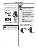
32 – English

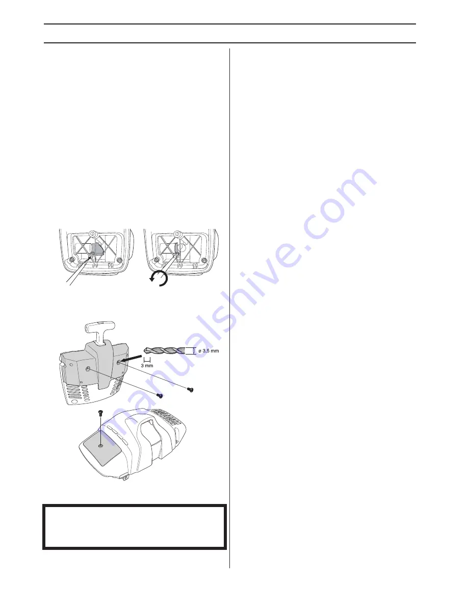
Winter use

Running problems can occur when using the machine in 
the cold and snowy conditions caused by:

Too low engine temperature.

Icing of the air filter and carburettor.

Special measures are therefore often required:

Partly mask the air inlet on the starter to increase the 
working temperature of the engine.

Preheat the intake air to the carburettor by using the 
heat from the cylinder.

Temperature 5

°°°°

C or colder:

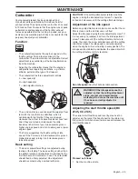
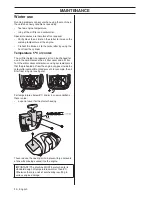
The air filter holder is prepared so it can be changed for 
use in the cold. Remove the air filter cover and air filter. 
Turn the winter cover anticlockwise using a screwdriver so 
that the preheated air from the engine can pass inside the 
carburettor compartment and prevent, for example, the air 
filter from icing up (see figure).

For temperatures below 5

°

C and/or in snow conditions 

there is also:

a special cover for the starter housing

These reduce the cooling air and prevent large amounts 
of snow from being sucked into the engine.

IMPORTANT! The machine MUST be returned to its 
standard design at temperatures warmer than 5

°

C . 

Otherwise there is a risk of overheating resulting in 
serious engine damage.

Summary of Contents for BC2145

Page 1: ...English FC2145 FC2145S BC2145 FC2145W CC2145 Operator s manual Please read the operator s manual carefully and make sure you understand the instructions before using the machine ...

Page 2: ...etres Machines fitted with saw blades or grass blades can be thrown violently to the side when the blade comes into contact with a fixed object This is called blade thrust The blade is capable of amputating an arm or leg Always keep people and animals at least 15 metres from the machine Always wear approved protective gloves Wear sturdy non slip boots Only use non metallic flexible cutting attachm...

Page 3: ...sh cutter 19 Standard harness 19 Vector harness 19 FUEL HANDLING Fuel safety 21 Fuel 21 Fuelling 22 STARTING AND STOPPING Check before starting 23 Starting and stopping 23 WORKING TECHNIQUES General working instructions 25 MAINTENANCE Carburettor 29 Muffler 30 Cooling system 30 Air filter 30 Bevel gear 31 Drive shaft 31 Spark plug 31 Winter use 32 Maintenance schedule 33 TECHNICAL DATA Technical d...

Page 4: ...lers ask for the address of your nearest service workshop It is our wish that you will be satisfied with your product and that it will be your companion for a long time Think of this operator s manual as a valuable document By following its content using service maintenance etc the life span and the second hand value of the machine can be extended If you will sell this machine make sure that the b...

Page 5: ...ut 10 Support eyes for harness 11 Cylinder cover 12 Starter handle 13 Fuel tank 14 Choke control 15 Air purge 16 Air filter cover 17 Handle adjustment 18 Locking screw 19 Support cup 20 Support flange 21 Drive disc 22 Trimmer head 23 Spark plug cap and spark plug 24 Socket spanner 25 Operator s manual 26 Transport guard for cutting equipment 27 Allen key 28 Carburettor screwdriver 29 Locking pin 3...

Page 6: ...witch 9 Throttle lockout 10 Support eyes for harness 11 Cylinder cover 12 Starter handle 13 Fuel tank 14 Choke control 15 Air purge 16 Air filter cover 17 Handle adjustment 18 Locking nut 19 Support flange 20 Drive disc 21 Spark plug 22 Socket spanner 23 Operator s manual 24 Transport guard for cutting equipment 25 Allen key 26 Carburettor screwdriver 27 Locking pin 28 Harness FC 2145 29 Harness F...

Page 7: ...Stop switch 9 Throttle lockout 10 Support eyes for harness 11 Cylinder cover 12 Starter handle 13 Fuel tank 14 Choke control 15 Air purge 16 Air filter cover 17 Handle adjustment 18 Locking screw 19 Support cup 20 Support flange 21 Drive disc 22 Trimmer head 23 Spark plug cap and spark plug 24 Socket spanner 25 Operator s manual 26 Transport guard 27 Allen key 28 Carburettor screwdriver 29 Locking...

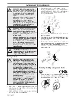
Page 8: ...Maintenance All covers guards and handles must be fitted before starting Ensure that the spark plug cap and ignition lead are undamaged to avoid the risk of electric shock The machine operator must ensure that no people or animals come closer than 15 metres while working When several operators are working in the same area the safety distance should be at least twice the tree height and no less tha...

Page 9: ...This movement is controlled by two independent return springs This arrangement means that the throttle control is automatically locked at the idle setting Make sure the throttle control is locked at the idle setting when the throttle lockout is released Press the throttle lockout and make sure it returns to its original position when you release it Check that the throttle control and throttle lock...

Page 10: ...achine s vibration damping system reduces the transfer of vibration between the engine unit cutting equipment and the machine s handle unit Regularly check the vibration damping units for cracks or deformation Check that the vibration damping element is undamaged and securely attached Quick release There is an easily accessible quick release fitted at the front as a safety precaution in case the e...

Page 11: ... arrestor mesh this must be cleaned regularly A blocked mesh will cause the engine to overheat and may lead to serious damage Locking nut A locking nut is used to secure some types of cutting attachment When fitting tighten the nut in the opposite direction to the direction of rotation of the cutting attachment To remove it undo the nut in the same direction as the cutting attachment rotates CAUTI...

Page 12: ...recommend See the chapter on Technical data Keep the teeth of the blade correctly sharpened Follow our instructions and use the recommended file gauge An incorrectly sharpened or damaged blade increases the risk of accidents IMPORTANT Only use cutting attachments with the guards we recommend See the chapter on Technical data Refer to the instructions for the cutting attachment to check the correct...

Page 13: ...rpening instructions A correctly sharpened blade is essential for working efficiently and to avoid unnecessary wear to the blade and brush cutter Make sure that the blade is well supported when you file it Use a 5 5 mm round file with a file holder The filing angle is 15 File alternate teeth to the right and those in between to the left If the blade has been heavily pitted by stones it may be nece...

Page 14: ...ng a cord the engine must throw out the cord radially from the trimmer head and overcome the resistance of the grass being cleared The length of the cord is also important A longer cord requires greater engine power than a shorter cord of the same diameter Make sure that the cutter on the trimmer guard is intact This is used to cut the cord to the correct length To increase the life of the cord it...

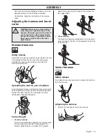
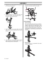
Page 15: ...dlebar as shown Fit the mounting components and tighten the knob lightly Put on the harness and hang the machine from the support hook Now make a final adjustment so that the machine is in a comfortable working position when it hangs from the harness Tighten the knob Assembling the handlebar and throttle FC 2145 FC 2145 S FC 2145 W Unscrew the knob from the handlebar mounting Position the handleba...

Page 16: ...pposite side of the shaft Use the locking pin C Place the locking pin in the groove on the screw head and tighten See diagram CAUTION Always use the recommended guard for the cutting attachment you are using See chapter on Technical data Fit the drive disc B on the angle gear s output shaft WARNING When fitting the cutting attachment it is extremely important that the raised section on the drive d...

Page 17: ...ata Fit the drive disc B on the output shaft Turn the blade shaft until one of the holes in the drive disc aligns with the corresponding hole in the gear housing Insert the locking pin C in the hole to lock the shaft Place the blade D and support flange F on the output shaft Fit the nut G The nut must be tightened to a torque of 35 50 Nm 3 5 5 kpm Use the socket spanner in the tool kit Hold the sh...

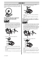
Page 18: ... gear housing Insert the locking pin C in the hole to lock the shaft Screw on the trimmer head H in the opposite direction to the direction of rotation Tighten the trimmer head to a torque of 35 50 Nm 3 5 5 kpm To dismantle follow the instructions in the reverse order Fitting other guards and cutting attachments Fit the trimmer guard combination guard A intended for use with the trimmer head plast...

Page 19: ...ed across both shoulders Correct height 1 Forestry clearing The machine should be supported in a harness when forestry clearing so that the cutting equipment is angled slightly forwards in relation to the ground Adjust the height using the strap on the harness for the support hook 2 Grass clearing The machine should be supported in a harness when grass clearing so that the cutting equipment is par...

Page 20: ... A to the lower mounting point on the backplate 6 The elastic strap B can be tightened to transfer more load from the shoulder straps to the hip strap Correct balance 1 Forestry clearing The machine is balanced by moving the suspension ring on the machine forwards or backwards On some models the suspension ring is fixed however this will then have a number of holes for the support hook The machine...

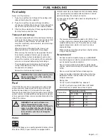
Page 21: ...astically affect the ratio of the mixture Petrol CAUTION Always use a quality petrol oil mixture at least 90 octane RON If your machine is equipped with a catalytic converter see chapter onTechnical data always use a good quality unleaded petrol oil mixture Leaded petrol will destroy the catalytic converter Use low emission petrol also known as alkylate petrol if it is available The lowest octane ...

Page 22: ... Contamination in the tank can cause operating problems Ensure that the fuel is well mixed by shaking the container before filling the tank WARNING The catalytic converter muffler gets very hot during and after use This also applies during idling Be aware of the fire hazard especially when working near flammable substances and or vapours WARNING Taking the following precautions will lessen the ris...

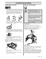
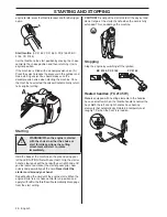
Page 23: ...rectly fitted and undamaged before you start the machine Starting and stopping Cold engine Ignition Set the stop switch to the start position Choke Set the choke control A in the choke position Primer bulb Press the air purge diaphragm B repeatedly until fuel begins to fill the diaphragm The diaphragm need not be completely filled Warm engine Use the same starting procedure as for a cold engine bu...

Page 24: ...resistance the starter pawls grip now quickly and powerfully pull the cord Never twist the starter cord around your hand Repeat pulling the cord until the engine starts When the engine starts return choke control to run position and apply full throttle the throttle will automatically disengage from the start setting CAUTION Do not pull the starter cord all the way out and do not let go of the star...

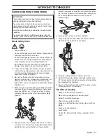
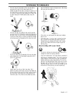
Page 25: ...sition before or after being cut If you position yourself incorrectly or make the cut in the wrong place the tree may hit you or the machine and cause you to lose control Both situations can cause serious personal injury 6 Keep a good balance and a firm foothold 7 Always hold the machine with both hands Hold the machine on the right side of your body 8 Keep the cutting attachment below waist level...

Page 26: ...ore you remove material that has wound around the blade shaft as otherwise there is a risk of injury The bevel gear can get hot during use and may remain so for a while afterwards You could get burnt if you touch it WARNING Watch out for thrown objects Always wear approved eye protection Never lean over the cutting attachment guard Stones rubbish etc can be thrown up into the eyes causing blindnes...

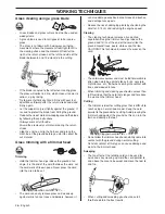
Page 27: ...first cut on the felling side Then finish cutting the stem from the other side Adjust the cutting pressure to match the size of the stem and the hardness of the wood Small stems require more pressure while large stems require less pressure If the stems are tightly packed adapt your walking pace to suit If the blade jams in a stem never jerk the machine free If you do this the blade bevel gear shaf...

Page 28: ...he cord can easily remove grass and weeds up against walls fences trees and borders however it can also damage sensitive bark on trees and bushes and damage fence posts Reduce the risk of damaging plants by shortening the cord to 10 12 cm and reducing the engine speed Clearing The clearing technique removes all unwanted vegetation Keep the trimmer head just above the ground and tilt it Let the end...

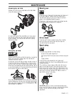
Page 29: ...nti clockwise gives a lower idle speed Basic setting The basic carburettor settings are adjusted during testing at the factory The basic setting is richer than the optimal setting and should be maintained for the first few hours the machine is in use The carburettor should then be finely adjusted Fine adjustment should be carried out by a skilled technician CAUTION If the cutting attachment rotate...

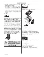
Page 30: ... checked and if necessary cleaned monthly If the mesh is damaged it should be replaced If the mesh is frequently blocked this can be a sign that the performance of the catalytic converter is impaired Contact your dealer to inspect the muffler A blocked mesh will cause the machine to overheat and result in damage to the cylinder and piston CAUTION Never use a machine with a defective muffler Coolin...

Page 31: ...vel gear The bevel gear is filled with the right amount of grease at the factory However before using the machine you should check that the bevel gear is filled 3 4 full with grease Use JONSERED special grease The grease in the bevel gear does not normally need to be changed except if repairs are carried out Drive shaft The drive shaft must be greased every three months during full time use Contac...

Page 32: ...red so it can be changed for use in the cold Remove the air filter cover and air filter Turn the winter cover anticlockwise using a screwdriver so that the preheated air from the engine can pass inside the carburettor compartment and prevent for example the air filter from icing up see figure For temperatures below 5 C and or in snow conditions there is also a special cover for the starter housing...

Page 33: ...upport cup with bearings X Check that the transport guard for the blade is intact and that it can be secured correctly X Check that nuts and screws are tight X Check that there are no fuel leaks from the engine tank or fuel lines X Check the starter and starter cord X Check that the vibration damping elements are not damaged X Clean the outside of the spark plug Remove it and check the electrode g...

Page 34: ... 13500 13500 13500 Speed of output shaft rpm 9000 10500 10500 10500 Max engine output acc to ISO 8893 kW rpm 2 0 9000 2 0 9000 2 1 9600 2 1 9600 Catalytic converter muffler Yes No Yes Yes Speed regulated ignition system Yes Yes Yes Yes Ignition system Spark plug Champion RCJ 6Y Champion RCJ 6Y Champion RCJ 6Y Champion RCJ 6Y Electrode gap mm 0 5 0 5 0 5 0 5 Fuel and lubrication system Fuel tank ca...

Page 35: ...ke mm 32 5 Idle speed rpm 2800 Recommended max speed rpm 12500 Speed of output shaft rpm 9000 Max engine output acc to ISO 8893 kW rpm 2 0 9000 Catalytic converter muffler No Speed regulated ignition system Yes Ignition system Spark plug Champion RCJ 6Y Electrode gap mm 0 5 Fuel and lubrication system Fuel tank capacity litre 0 9 Weight Weight without fuel cutting attachment and guard kg 8 2 Noise...

Page 36: ...3 3 mm cord 503 95 43 04 Support cup Fixed With ball bearing FC 2145 FC 2145 S FC 2145 W Approved accessories Type Cutting attachment guard Art no Centre hole in blades cutters Ø 25 4 mm Output shaft thread M12 Grass blade grass cutter Multi 255 3 Ø 255 3 teeth 537 29 74 02 Multi 275 4 Ø 275 4 teeth 537 29 74 02 Multi 300 3 Ø 300 3 teeth 537 29 74 02 Saw blade Opti XS 200 22 Ø 200 22 teeth 537 21 ...

Page 37: ...an 3 SE 754 50 Uppsala Sweden has performed voluntary type examination on behalf of Husqvarna AB The certificates are numbered SEC 09 2188 01 164 042 01 164 043 BC 2145 SEC 09 2190 01 164 041 FC 2145 SEC 09 2190 01 164 040 FC 2145 S FC 2145 W SEC 09 2189 01 164 042 01 164 043 CC 2145 Huskvarna December 29 2009 Bo Jonsson Development manager Authorized representative for Husqvarna AB and responsibl...

Page 38: ...1 Poly Trim 2 3 4 5 6 7 8 20mm 20mm B A 6 Nm X 10 ...

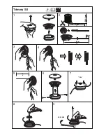
Page 39: ...1 2 3 4 5 6 7 8 9 35 50 NM 15 cm 6 Clic 3 5 m 11 7 0 m 23 2 4 3 3 mm 095 130 12 cm 5 Trimmy SII ...

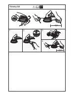
Page 40: ......

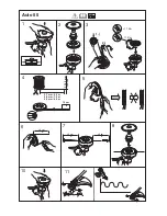
Page 41: ...2 7 3 3 mm 106 130 15 cm 6 15 cm 6 15 cm 6 15 cm 6 1 2 3 5 6 7 10 11 1 2 1 1 Kw 1 1 Kw 2 7 mm 9 0 m 3 0 mm 7 5 m 3 3 mm 6 0 m 4 8 Auto 55 ...

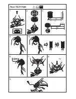
Page 42: ... Clic 1 2 3 5 6 7 9 10 m 32 4 8 4 3 m 14 2 7 3 3 mm 106 13 10 cm 4 6 15 cm Tap n Go 45 Spin ...

Page 43: ......

Page 44: ...1153306 26 z U 6i z U 6i 2010 03 19 Original instructions ...

Reviews: