background image

51

LUBRICATION

51

Transmission Purging Procedures

Due to the effects air has on efficiency in hydrostatic 
drive applications, it is critical to purge the system.
These purge procedures should be implemented 
any time a hydrostatic system has been opened to 
facilitate maintenance or any additional oil has been 
added to the system.
Resulting symptoms in hydrostatic systems may be:
•  Noisy operation.
•  Lack of power or drive after short term operation.
•  High operation temperature and excessive 

expansion of oil.

Before starting, make sure the oil tank is at the proper 
oil level. If not, fill to the specifications outlined in this 
section.
The following procedures are best performed with the 
vehicle drive wheels off the ground, then repeated 
under normal operating conditions.
1.  Disengage the brake if activated.
2.  With the bypass valve open and the engine 

running at fast idle, slowly move the directional 
control in both forward and reverse directions (5 
or 6 times). As air is purged from the unit, the oil 
level will drop.

3.  With the bypass valve closed and the engine 

running, slowly move the directional control in 
both forward and reverse directions (5 to 6 times). 
Check the oil level and add oil as required after 
stopping the engine.

4.  It may be necessary to repeat Steps 2 and 3 until 

all the air is completely purged from the system. 
When the hydraulic drive operates at normal noise 
levels and moves smoothly forward and reverse at 
normal speeds, the hydraulic drive is considered 
purged.

5.  After the vehicle has been used two times, the oil 

level should be checked while the oil is cold and 
adjusted accordingly.

Summary of Contents for 966614003

Page 1: ...arefully and make sure you understand the instructions before using the machine Gasoline containing up to 10 ethanol E10 is acceptable for use in this machine The use of any gasoline exceeding 10 ethanol E10 will void the product warranty PZ54 966614003 ...

Page 2: ...information contained in these instructions Use only original parts for repairs The use of other parts voids the warranty Do not modify or install non standard equipment to the unit without consent from the manufacturer Modifications to the unit may cause unsafe operations or damage the unit When this product is worn out and no longer used it should be returned to the reseller or other party for r...

Page 3: ...ety Belt 27 Before Starting 27 Starting the Engine 28 Jumper Cables Use 30 Running 31 Operating on Hills 32 Mowing Tips 33 Stopping the Engine 34 Moving Machine By Hand 35 Bypass Valves 35 MAINTENANCE 36 Battery 38 Safety System 39 Fuel Filter 39 Tire Pressures 39 Parking Brake 40 Parking Brake Adjustments 40 Deck Belt 42 Pump Belt 43 V belts 43 Cutting Blades 44 Adjusting the Mower Deck 45 Leveli...

Page 4: ...nd mind and body and must not be under the influence of any mind altering substance WARNING Engine exhaust some of its constituents and certain vehicle components contain or emit chemicals known to the State of California to cause cancer and birth defects or other reproductive harm WARNING Battery posts terminals and related accessories contain lead and lead compounds chemicals known to the State ...

Page 5: ...ing equipment and ensure that the machine is well anchored DO NOT operate this machine on public roadways Towing If machine is equipped with a tow hitch use extreme caution when towing Never allow children or others in or on the towed equipment Make wide turns to avoid jack knifing Travel slowly and allow extra distance to stop Do not tow on sloped ground The weight of the towed equipment may caus...

Page 6: ...he machine with the manufacturing number Engine Transmission Manufacturing Number The machine s manufacturing number can be found on the printed plate affixed to the right side in the engine compartment Stated on the plate from the top are The machine s type designation I D The manufacturer s type number Model The machine s serial number Serial no Please have the type designation and serial number...

Page 7: ...o notify the reader of a risk of material damage particularly if the reader should neglect to follow instructions given in the manual Used also when there is a potential for misuse or misassembly Reverse Neutral Fast Slow Choke Fuel Warning Parking Brake CE conformity marking Only for European market Do not stand here Use protective gloves Use protective glasses IMPORTANT INFORMATION Xxxx xxxxxx x...

Page 8: ...tor s Manual Shut off engine and remove key before performing any maintenance or repair work Keep a safe distance from the machine Use on slopes no greater than 10 No passengers Whole body exposure to thrown objects Severing of fingers and toes Do not open or remove safety shields while engine is running Careful backing up watch for other people Careful going forward watch for other people ...

Page 9: ...ep clear of the discharge opening at all times Only allow responsible adults who are familiar with the instructions to operate the machine Clear the area of objects such as rocks toys wire etc which could be picked up and thrown by the blades Be sure the area is clear of bystanders before operating Stop machine if anyone enters the area Never carry passengers The machine is only intended for use b...

Page 10: ...tion when operating machine Wear proper Personal Protective Equipment PPE while operating this machine including at a minimum sturdy footwear eye protection and hearing protection Do not mow in shorts and or footwear with open toes Data indicates that operators age 60 years and above are involved in a large percentage of riding mower related injuries These operators should evaluate their ability t...

Page 11: ...all grass can hide obstacles Choose a low ground speed so that you will not have to stop while on the slope Do not mow on wet grass Tires may lose traction Avoid starting stopping or turning on a slope If the tires lose traction disengage the blades and proceed slowly straight down the slope Keep movement on the slopes slow and gradual Do not make sudden changes in speed or direction which could c...

Page 12: ...assume that children will remain where you last saw them Keep children out of the mowing area and in the watchful care of a responsible adult other than the operator Be alert and turn machine off if a child enters the area Before and while backing look behind and down for small children Never carry children even with the blades shut off They may fall off and be seriously injured or interfere with ...

Page 13: ...e a vehicle or on a truck or trailer bed with plastic liner Always place containers on the ground away from the vehicle when filling Remove gas powered equipment from the truck or trailer and refuel it on the ground If this is not possible refuel such equipment with a portable container rather than from a gasoline dispenser nozzle Keep the nozzle in contact with the rim of the fuel tank or contain...

Page 14: ...rp Wrap the blade or wear gloves and use extra caution when servicing them Check brake operation frequently Adjust and service as required Maintain or replace safety and instruction labels as necessary Do not modify safety equipment Check regularly to be sure it works properly The machine must not be driven with defective or unmounted protective plates protective cowlings safety switches or other ...

Page 15: ...mes contain carbon monoxide an odorless poisonous and lethal gas Stop to inspect the equipment if you run over or into anything If necessary make repairs before starting Never make adjustments with the engine running The machine is tested and approved only with the equipment originally provided or recommended by the manufacturer Only use approved repair parts for the machine The blades are sharp a...

Page 16: ... on the unit and is attached to the engine muffler This mower is equipped with an internal combustion engine and should not be used on or near any unimproved forested bush covered or grassy lands unless the engine s system is equipped with a spark arrestor meeting applicable local or state laws if any In the state of California the above is required by law Section 4442 of the California Public Res...

Page 17: ...ns starts or stops When mower is stopped set brakes securely and use park brake If any part of ROPS is damaged the entire ROPS must be replaced Check all bolts including seat belt for correct torque before each use Check ROPS structure for damage before each use ROPS bar is NOT intended for use in sub zero temperatures WARNING The rollover protection system s capabilities may be impaired by damage...

Page 18: ...aulic pumps Using the left and right steering controls the flow is regulated and thereby the direction and speed Control Locations 1 2 3 4 5 6 8 9 10 12 7 11 13 1 Motion control levers 2 Tracking knob 3 Parking brake 4 Fuel tank cap left 5 Fuel tank cap right 6 Fuses 7 Hour meter 8 Ignition switch 9 Choke control 10 Throttle control 11 Blade switch 11 Seat adjustment lever 12 Deck lift 13 Deck rel...

Page 19: ...is reduced and the machine turns to the right Zero turn can be achieved by moving one control backward behind the neutral position and carefully moving the other steering control forward from its neutral position The rotation direction when zero turning is determined by which steering control is moved backward behind the neutral position If the left steering control is pulled backward the machine ...

Page 20: ...en applying the parking brake Always set the parking brake before dismounting Release the parking brake before moving the mower 8065 006 Parking brake 8065 085 Throttle control Throttle Control The throttle control regulates the engine speed and the rate of rotation of the blades assuming the blade switch is pulled out To increase or decrease the engine speed the control is moved forward or back r...

Page 21: ...tion when the engine has started For using ACCESSORY turn the key clockwise 8065 057 Ignition switch accessory Ignition Switch The ignition key is placed on the control panel and is used to start and stop the engine Turn the key clockwise to start the engine 8065 058 Ignition switch ...

Page 22: ...obiles There are three fuses with ratings and functions 1 20 A Primary fuse 2 7 5 A Mower deck coupling 3 10 A Accessories 8065 043 Fuses Hour Meter The hour meter displays the total operating time with the blade activated The display on the hour meter will turn on the oil can icon after every fifty hours of use and will stay on for two hours or until the meter is manually reset To manually reset ...

Page 23: ...made using the tracking bolt and tracking knob The tracking bolt and tracking knob act as limiting devices for the motion control levers when in the full forward position 2 For preliminary tracking adjustment move unit to an open unobstructed area such as an empty parking lot or open field 3 Back the tracking bolt out until flush with nut 4 Loosen tracking knob out until flush with nut 5 Test oper...

Page 24: ...er is moved upward Adjustments may be made to seat suspension by turning the center knob 8065 009 Lengthways adjustment Fuel Selection Valve The fuel shut off valve is located at the right rear of the seat The valve has three positions right tank left tank and OFF 8065 010 Fuel shut off valve in the CLOSED position IMPORTANT INFORMATION Seat should not be adjusted while unit is in motion ...

Page 25: ...peration Risk for burns if touched Allow engine and exhaust system to cool before refueling WARNING Fill to bottom of filler neck Do not overfill Wipe off any spilled oil or fuel Do not store spill or use gasoline near an open flame 8065 007 Gasoline fuel tanks IMPORTANT INFORMATION It is recommended that fuel be added to both tanks on initial start up Read the safety instructions before refueling...

Page 26: ...nearby To move unit under its own power the operator must be in the seat start engine see Before Starting in the Operation section adjust engine speed to idle disengage parking brake do not engage blades at this time rotate control levers inward As long as the control levers have not been moved forward or backwards mower will not move Slowly move both control levers forward slightly This will allo...

Page 27: ...y to lower roll bar do not wear the seat belt Raise the roll bar as soon as clearance permits 8065 011 Roll bar in upright position WARNING The seat belt must be used when the roll bar is in upright position 8065 110 Seat adjustment 8065 016 Set deck to selected cutting height 5 Set the pin at desired cutting height Height selection pin is removed by rotating 180O Make sure that the pin is inserte...

Page 28: ...y forward 3 Activate the parking brake 4 Disengage the mower blades by pressing the blade switch downwards 8065 085 Press the control for disengaging the mower deck 8065 017 Set mower deck to the transport position 5 Move the steering controls outward to the locked outer neutral position 8065 108 Place controls in neutral position ...

Page 29: ...age The engine exhaust contains carbon monoxide which is an odorless colorless poisonous gas Do not use the machine in enclosed spaces 10 When the engine starts immediately release the ignition key back to the run position 11 Push the choke control in gradually when the engine has started 12 Set the engine speed with the throttle Allow the engine to run at a moderate speed approximately mid thrott...

Page 30: ...OUND on the mower with the discharged battery away from the fuel tank and battery To remove cables reverse order 4 Remove BLACK cable first from chassis and then from the fully charged battery 5 Remove RED cable last from both batteries 8011 642 Jumper cable connection IMPORTANT INFORMATION The mower is equipped with a 12 volt negative grounded system The other vehicle must also be a 12 volt negat...

Page 31: ...al position N 3 Release deck height control by applying equal pressure to both pedals Push pedals again to lower deck to selected setting 4 Move throttle control to full throttle 5 Engage the mower deck by pulling out the blade switch 8065 006 Release the parking brake WARNING Make sure that no one is near mower when engaging blade switch Make sure the work area is free from objects that could be ...

Page 32: ...eed possible should be used before starting up or down hills Avoid stopping or changing speed on hills If stopping is absolutely necessary pull drive levers into the neutral position and push to the outside of the unit and engage the parking brake 8065 108 Place controls in neutral position To restart movement release the parking brake Pull the control levers back to the center of the mower and pr...

Page 33: ... The lawn becomes more even and the grass clippings more evenly distributed over the mown area The total time taken is not increased as a higher operating speed can be used without poor mowing results Avoid mowing wet lawns The mowing result is poorer because the wheels sink into the soft lawn clumps build and the grass clippings fasten under the cowling Hose the mower deck underside with water af...

Page 34: ...ding still activate the parking brake by pulling the lever upward 6 Turn the ignition key to the stop position If the engine has been worked hard allow it to idle a minute in order to attain a normal operating temperature before stopping To prevent fouling the spark plugs avoid idling the engine for longer periods 7 Remove key To prevent unauthorized use always remove key when leaving the mower 80...

Page 35: ...by hand when not running IMPORTANT INFORMATION Tighten the valve moderately Do not overtighten the valve when closing That can damage the valve seat 8065 061 Remove fan cover to access release valves Hydro Pumps Pump release valves are located at the front and rear of the pump Tilt the seat forward and remove the fan cover to gain access to the pump Use a 5 8 wrench or socket and ratchet Turn the ...

Page 36: ... around the engine Clean around belts belt pulleys Check the tire pressures Check battery connections Sharpen3 Replace mower blades Clean the engine s cooling air intake 2 Clean the air cleaner s foam pre filter 2 Clean the air cleaner s paper filter cartridge 2 Check adjust the parking brake Inspect muffler spark arrester 1 First change after 8 10 hours When operating with a heavy load or at high...

Page 37: ...ce the engine oil filter Clean replace the spark plugs Replace the fuel filter Replace paper air filter 2 Check the caster wheels every 200 hours Replace the air cleaner s foam pre filter 2 Check the hydraulic oil in the oil tank Change the hydraulic oil every 500 hours Replace the hydraulic oil filter every 500 hours Dismantle and inspect starter 3 every 500 hours Check adjust the mower deck Chec...

Page 38: ... CHARGE 12 4V 75 20 min 35 min 48 min 90 min 12 2V 50 45 min 75 min 95 min 180 min 12 0V 25 65 min 115 min 145 min 280 min 11 8V 0 85 min 150 min 195 min 370 min Charging time depends on battery capacity condition age temperature and efficiency of charger Battery Removal Corrosion and dirt on the battery and terminals can cause the battery to lose power 1 Lift the seat and rotate fully forward unt...

Page 39: ...ves off the driver s seat IMPORTANT INFORMATION To be able to drive the driver must sit in the seat and release the parking brake before the steering controls can be moved into the neutral position otherwise the engine will stop 8065 021 Conditions for starting Fuel Filter Replace the line mounted fuel filter every 100 hours once per season or more often if it becomes clogged 1 Move the hose clamp...

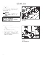
Page 40: ...006 Parking brake WARNING Faulty adjustment result in reduced braking ability and can cause an accident Parking Brake Adjustments 1 Using a jack stand raise the rear of the mower up off the ground Make sure the machine is securely supported 2 Remove the rear tire assemblies 3 Release the park brake 4 Measure the distance from the swivel to the washer See Illustration The measurement should be 1 on...

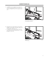
Page 41: ... A jam nut until the correct distance is achieved Retighten B jam nuts against A jam nuts 6 Engage the park brake Measure the distance between the D brake bolt and the brake swivel The distance should be 1 8 7 If adjustments are needed loosen C jam nut Turn the brake bolt until the distance is correct Retighten C jam nuts 8065 052 Measure gap ...

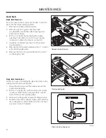
Page 42: ...leys 5 Remove the belt guide hardware with a wrench and set belt guide aside 6 Remove the belt from around the electric clutch on the engine shaft 8065 046 Remove belt guide Deck Belt Installation NOTE For ease in installing the deck belt refer to the routing decal on the cutting deck 1 Place the belt around all the pulleys except the center spindle pulley 2 With a breaker bar shift the idler arm ...

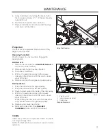
Page 43: ...e of the idler pulley 4 With a breaker bar and using the square opening in the idler arm shift the arm to create slack in the belt While holding the idler back with the breaker bar wrap the belt around the right pump pulley 5 Replace and secure clutch stop 6 Reinstall the deck belt See Deck Belt Installation in this section of the manual 8065 041 1 Electric clutch 2 Idler release placement 3 Clutc...

Page 44: ...pening Check the blade mounts Blade Replacement 1 Remove blade bolt by turning counterclockwise 2 Install new or re sharpened blade with stamped GRASS SIDE facing towards ground grass down or THIS SIDE UP facing deck and cutter housing 3 Install and tighten blade bolt securely 4 Torque blade bolt to 90 ft lbs 122 Nm 8065 028 1 Blade 2 Blade bolt special 3 Cutter housing Blade attachment IMPORTANT ...

Page 45: ... the opposite side check that measurement is the same If adjustment is required loosen the locknut and adjust bolt up until both side to side measurements are equal Retain measurement 3 Turn both outer blades to align with the deck in front to rear manner Reposition rear mounting bolts up or down until rear blade tips are positioned 1 8 to 3 8 higher in the rear than the front blade tips 4 Confirm...

Page 46: ...ower position 4 to 5 102 to 127 mm grass 8065 029 Anti scalp rollers 8065 030 1 Caster bolt 2 Axle spacer Caster wheel Caster Wheels Check every 200 hours Check that wheels rotate freely Removal and Installation Remove nut and caster bolt Pull the wheel out of the fork Install in reverse order Tighten caster bolt Torque to 45 ft lbs 61 Nm then back nut off turn NOTE Tire should rotate freely but a...

Page 47: ...r Avoid spraying engine and electrical components with water Do not rinse hot surfaces with cold water Let unit cool before washing Hardware Check daily Inspect the entire machine for loose or missing hardware Spark Arrestors A spark arrester is attached to the engine muffler Clean the interior screen regularly depending on usage and conditions To clean remove the clamp securing the tail pipe Remo...

Page 48: ...ith grease unless otherwise stated use high grade molybdenum disulphide grease For daily use the machine should be lubricated twice weekly Wipe away excess grease after lubrication It is important to avoid getting lubricant on the belts or the drive surfaces on the belt pulleys Should this happen attempt to clean them with spirits If the belt continues to slip after cleaning it must be replaced Ga...

Page 49: ...t wheels 8065 033 Deck spindle Deck Spindle Lower the cutting deck completely If a grease gun without rubber hose is used the foot plate must be removed Lubricate with a grease gun 2 3 strokes per spindle Cables If possible grease both ends of the cables and move the controls to end stop positions when lubricating Refit the rubber covers on the cables after lubrication Cables with sheaths will bin...

Page 50: ... Remove the oil filter from the pump Do not fill above this level Minimum fill level Drain old oil filters of all free flowing oil prior to disposal Place used oil in appropriate containers and dispose of it in accordance with laws in your area 3 After the oil has drained wipe the filter base surface off and apply a film of new oil to the gasket of the new replacement filter 4 Prefill the oil filt...

Page 51: ...ls off the ground then repeated under normal operating conditions 1 Disengage the brake if activated 2 With the bypass valve open and the engine running at fast idle slowly move the directional control in both forward and reverse directions 5 or 6 times As air is purged from the unit the oil level will drop 3 With the bypass valve closed and the engine running slowly move the directional control i...

Page 52: ...or contact of the battery terminal cable connections Blown fuse Fault in the starter safety circuit See Safety System in the Maintenance Section Engine runs rough Faulty carburetor Choke control is pulled out with a warm engine Clogged fuel filter or jet Clogged ventilation valve on the fuel cap Fuel tank nearly empty Fouled spark plugs Rich fuel mixture or fuel air mixture Wrong fuel type Water i...

Page 53: ... brake on Bypass valve on pump open Drive belt for the transmission slack or has come off Air trapped in hydraulic system Mower deck not engaging Drive belt for the mower deck has come loose Contact for the electromagnetic coupling has loosened Blade switch is faulty or has come loose from cable contact Blown fuse Transaxle leaks oil Damaged seals housing or gaskets Air trapped in hydraulic system...

Page 54: ... Empty the fuel tanks or add a fuel stabilizer Start the engine and allow it to run until the carburetor is drained of fuel or the stabilizer has reached the carburetor 5 Remove the spark plug and pour about a tablespoon of engine oil into the cylinder Turn over the engine so that the oil is evenly distributed and then refit the spark plug 6 Lubricate all grease zerks joints and axles 7 Remove the...

Page 55: ...WIRING DIAGRAM 55 TIMER SCHEMATIC ...

Page 56: ...peed forward 0 11 mph 0 17 7 Km h Speed reverse 0 6 mph 0 9 7 Km h Brakes Disc Front caster tires smooth tread 13 x 6 5 Flat Free Rear tires turf pneumatic 23 x 10 50 4 ply Tire pressures 15 PSI 103 kPa 1 bar 1 See the Engine Manufacturer s manual for engine specifications 2 The power rating of the engines indicated is the average net power output at specified rpm of a typical production engine fo...

Page 57: ...ble Sprung Seat Suspension Hinged Arm Rests Yes Hour Meter Yes Blade Engagement Ogura 3 5 Deck Construction 7 gauge Productivity 4 8 acres h 19 425 m2 h Dimension Weight 1260 lbs 572 kg Base Machine Length 82 210 cm Base Machine Height 47 121 cm Base Machine Width 52 132 cm Overall Width Chute Up 55 141 cm Overall Width Chute Down 68 173 cm Overall Height ROPS Up 72 183 cm ...

Page 58: ... or coarse thread 9 12 13 18 5 16 18 24 28 38 24 33 3 8 31 42 46 62 40 54 7 16 50 68 75 108 75 102 115 156 9 16 110 150 165 224 5 8 150 203 225 305 250 339 370 502 7 8 378 513 591 801 11 8 782 1060 1410 1912 Grade 5 Minimum commercial quality lower quality not recommended Metric Standard Hardware Grade Grade 8 8 Grade 10 9 Grade 12 9 Size ft lbs Nm ft lbs Nm ft lbs Nm Shank Size Diameter in inches...

Page 59: ...t the machine will fulfill the requirements This is also applicable to special requirements for any of the states California emission rules etc Do not remove any of these labels Certificates can also be supplied with the machine at delivery or written in the Engine manual Take care of them as they are valuable documents ...

Page 60: ...justment Check Safety switch for the parking brake Safety switch for the mower deck Safety switch in the seat Safety switch in the steering controls Parking brake functionality and adjustment Driving forward Driving backward Engaging the blades Check the idle speed Check the engine high idle speed Inform the customer about The need and advantages of following the service schedule The need and adva...

Page 61: ...gine oil Change the oil filter Check hydraulic oil level Inspect hydraulic hoses Inspect hydraulic belt Inspect hydraulic filter Check neutral position Check safety system Check seat belt Check ROPS Check fuel system for leaks Inspect safety guards and shields Check brake adjustment ...

Page 62: ...s from mower Check engine oil level Check the tire pressures Check underside of deck Inspect deck pulleys Check clean the engine s cooling air intake Check safety system Check seat belt Check ROPS Check fuel system for leaks Inspect safety guards and shields Check brake adjustment ...

Page 63: ...is from mower Check engine oil level Check the tire pressures Check underside of deck Inspect deck pulleys Check clean the engine s cooling air intake Check safety system Check seat belt Check ROPS Check fuel system for leaks Inspect safety guards and shields Check brake adjustment ...

Page 64: ... Inspect fuel filter Check engine RPM Clean underside of deck Check blade pitch Grease blade spindles Inspect spindle bearings Inspect deck belt and blades Inspect idler arm bearings Inspect deck idler pulleys Check hydraulic oil level Inspect hydraulic filter Inspect hydraulic drive belt Inspect hydraulic hoses Check neutral position Inspect battery connections Check safety system Check seat belt...

Page 65: ... RPM Clean underside of deck Check blade pitch Grease blade spindles Inspect spindle bearings Inspect deck belt and blades Inspect idler arm bearings Inspect deck idler pulleys Change hydraulic oil level Change hydraulic filter Replace hydraulic drive belt Inspect hydraulic hoses Check neutral position Inspect battery connections Load test battery Clean electrical connections Inspect the clutch Ch...

Page 66: ...ke Replace the air cleaner s pre filter foam Replace the air filter s paper cartridge Change the engine oil Replace the engine oil filter Check adjust the cutting height Check adjust the parking brake Clean Change the spark plugs Inspect spark plug Check the engine valve clearance Check the engine valve clearance ...

Page 67: ......

Page 68: ...115 520727 Rev A 2012 10 30 www husqvarna com ...

Reviews: