40
41
104 72 57-26
104 72 57-26
Circuit board - Circuit diagram - for models 350, 400
and 500 -
Dismounting
1. Dismount rear cover (see page 33-34).
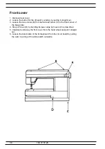
2. Dismount front cover (see page 35).
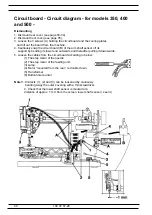
3. Loosen the 3 screws (A) holding the circuit board and the cooling plates
and lift out the board from the machine.
4. Cautiously snap the circuit board (B) of the arm shaft sensor off its
support by bending its lower end outwards and thereafter pulling it downwards.
5. Loosen the cables from the circuit board according to below:
(1) The step motor of the needle.
(2) The step motor of the feeding unit.
(3) Lamp.
(4) Motor ”mounted from the rear”, red cable down.
(5) Transformer
(6) Buttonhole counter
Note!
1.Contacts (1), (2) and (3) can be loosened by cautiously
bending away the outer covering with a thin screwdriver.
2. Check that the lower shaft sensor is mouted at a
distance of approx. 1 mm from the screen, lower shaft sensor ( see ill.)

